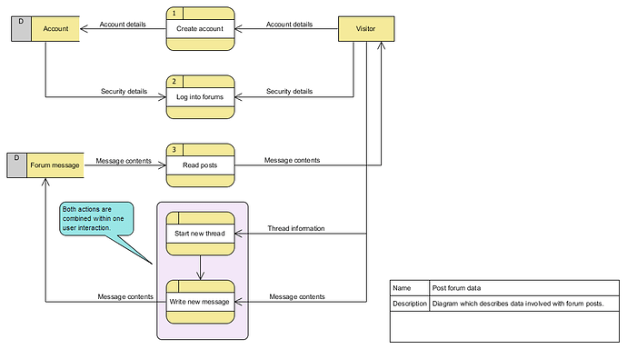
Editorial: It’s been a little longer than I anticipated, but I haven’t forgotten about this thread. I had to deal with a two-faced problem: first I set a little too high standard for myself (a very complex yet also very impressive diagram, I will address this in a later post) and my available time also got severely limited due to work obligations.
June 2018
The Data Flow Diagram (DFD)
The data flow diagram (“DFD”) is one of those hidden pearls within Visual Paradigm and it is easy to overlook. You can think of a DFD as a combination of a Use Case and a Communication diagram, both of which you can find within the UML specification.
There is no official standard for a DFD (just try looking it up on Google Images) and that’s also where its advantage lies. Sounds weird? It’s simple really: this allows you to set up a rough overview of your project and the involved data without having to worry about invalidating your diagram.
And that allows you to fully focus on the data and less on ensuring that you correctly comply to the current standards. To emphasize on this I added a small square and a shout-out box which provides us with some extra information.
Overview of used model elements
The diagram structure is really very simple, the whole diagram actually consists of only three main model elements:
- External Entities: These are entities which somehow interact with your system.
- Process: The specific task(s) which are supported by the system.
- Data Store: This represents the manifestation of certain data.
Specific enhancements
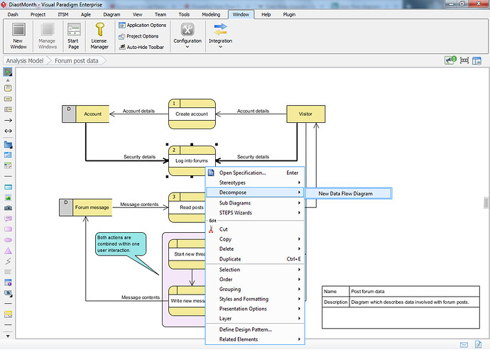
Visual Paradigm wouldn’t be Visual Paradigm if it didn’t provide us with some specific features unique to working with VP ![]() As you can see I can number my processes, I can create relations between them, but what if I want to further describe the detailed inner working of a process?
As you can see I can number my processes, I can create relations between them, but what if I want to further describe the detailed inner working of a process?
We could always consider to add a sub diagram but VP has something even better set up for us:
Decomposition!
Although this is basically the same thing as creating a new sub diagram it also provides a specific advantage: all the model elements which are related to your current process can be automatically added to the new diagram, which will make it a lot easier for you to work out your subprocess!
And as mentioned before: you don’t have to worry too much about specifications.
Availability
The Data Flow Diagram is available in Visual Paradigm Modeler and up.
Difficulty
On my personal difficulty rating (which goes from 1 to 5) I give this a 2 out of 5. The limited amount of required model elements combined with the resource catalog makes this a really easy diagram to get started with.
The reason I still set it to 2 is because despite its simplicity the DFD actually has some hidden settings which could slightly add to its complexity. For example, those Data Store model elements? They actually have 4 types for you to use:
- Computerized data (as shown in my example).
- Manual
- Transient data file
- Transient manual
Although this doesn’t make it too complex it’s still something to keep in mind.
And there you have it!
The next time you’re struggling a little bit with structuring your project, especially if that involves compliancy with current standards, then maybe this diagram can help you focus by setting up a rough overview.


