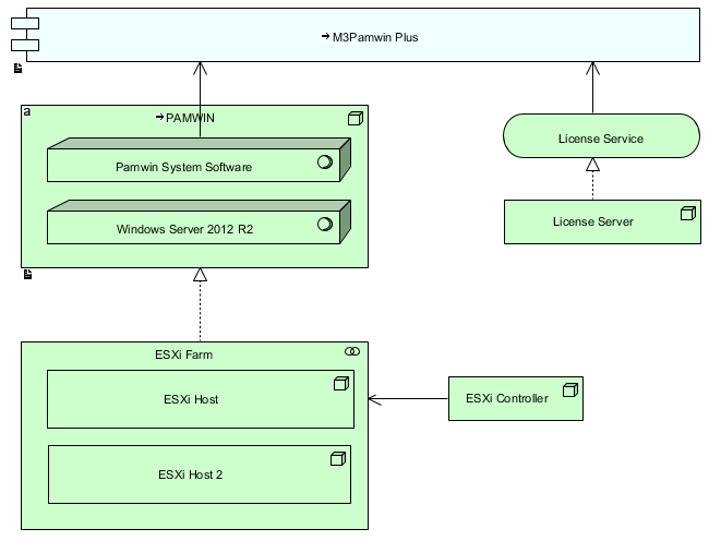
I would like to show the chain of dependencies in an Impact Analysis chart so that columns represent technology elements that are to be upgraded, rows should show all applications, services or other nodes that would be affected by the upgrade.
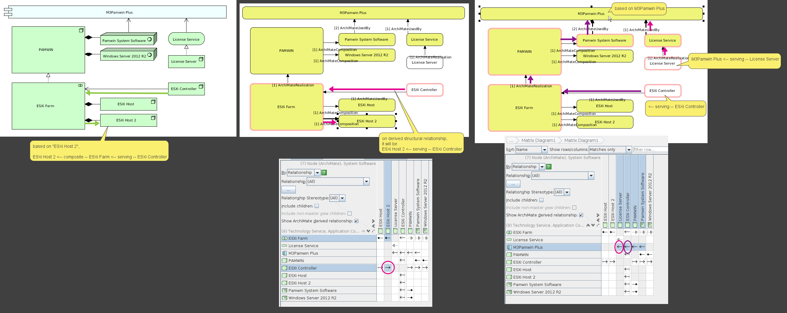
The full impact analysis for the diagram looks like Fig. 2.
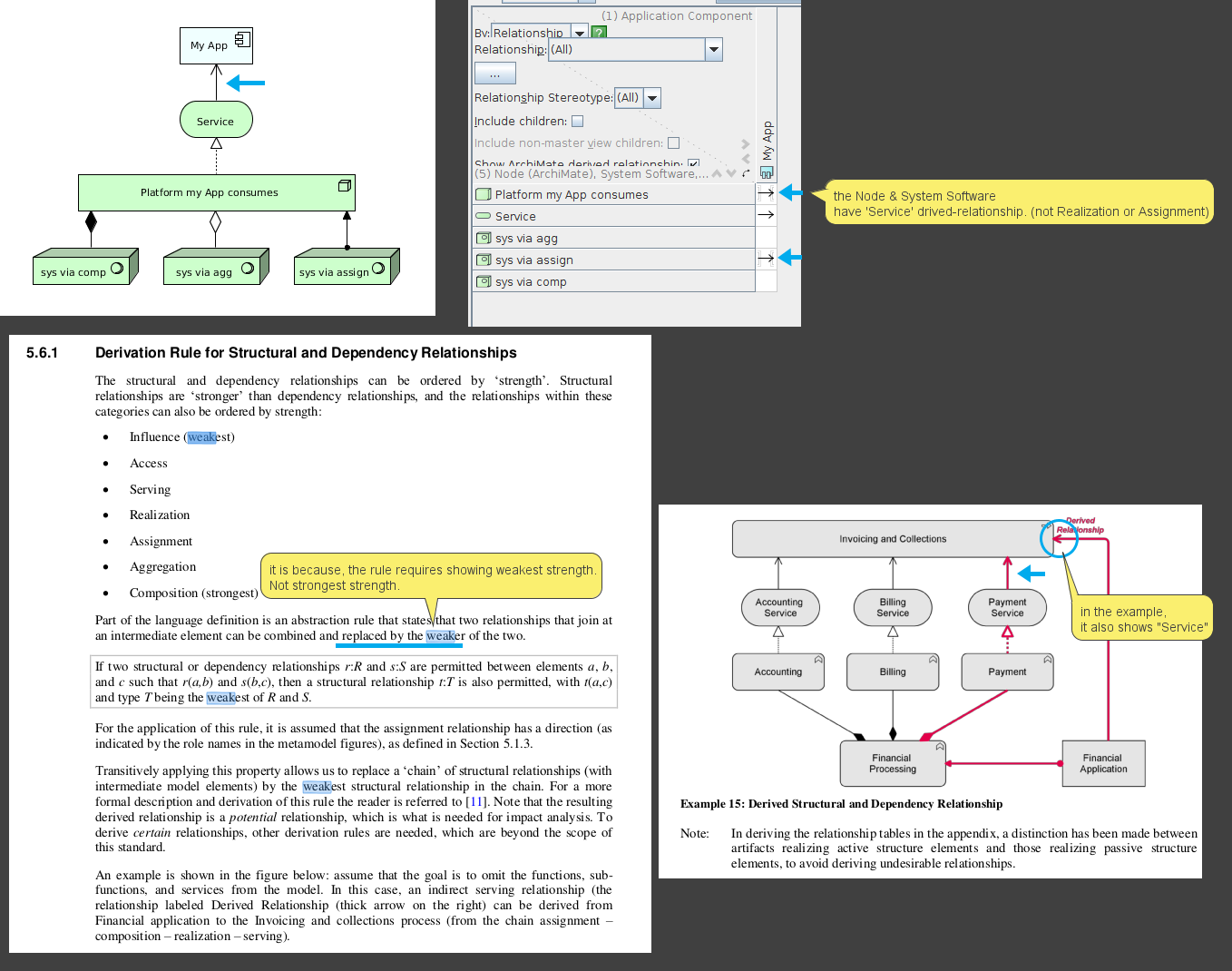
When filtered on the component to be upgraded, like Fig. 3:
How can I show all applications affected if the host is upgraded? I would have thought that “Show Archimate derived relationship” checkbox would enable this to happen.
Sorry, it is a bug.
In ArchiMate 3.0, the rules of derived-relationships is different from ArchiMate 2.0.
But we are missing to update our logic to support ArchiMate 3.0’s derived-relationships.
Thank you for investigating this issue. I am please that you can confirm the bug and look forward to the hotfix/patch.
I am well aware of the complexities of ArchiMate 3.0 relationships. I believe the Open Group specification for relationships was rather flawed when it was first released.
Archimate is an ideal bridge between our business (BPMN) and engineering (UML) worlds, so I’ll be pleased to see Impact analysis able to correctly identify dependencies.
The patch for v15.1 is ready.
Please update the software to latest patch build (20190430ab or later) to get the problem fixed.
Details about update to latest patch can be found at
Interesting use of collaboration there chris
Funnily enough VP is one of the few tools that does derived properly.
Its not on the certification critera as a function to be provided.
Which is what means some of the other tool that lack this still get certified largely becuase they can draw a diagram
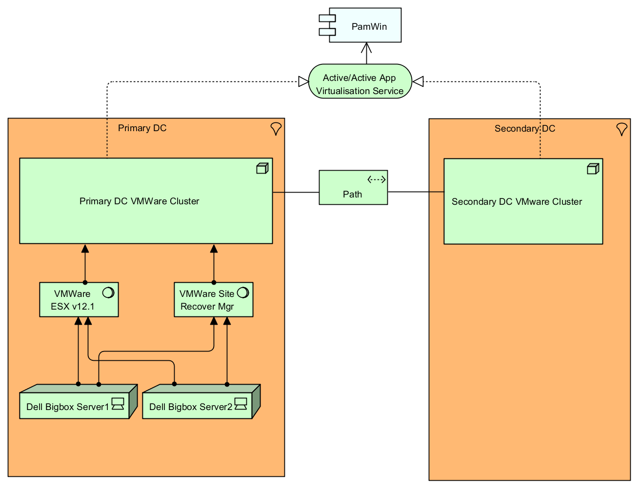
Might be more robust if u “offer” up the VMWare Farm as a service to the app layer. So then you alway use the serves relationship as you go up and down the layers. I played with collaboration but I find it just gets in the way and didnt add anything helpful that service didnt already say. “that dutch chap” thinks they are a bit of an antipattern belw bus level
Hi,
I agree, my sample is not consistent in the use of services at the interface between architecture layers.
Gerben Wierda (“that dutch chap”) does show a number of patterns for collaboration, including:
The collaboration entity
Using Aggregation/Composition relationships, e.g. where the ESXi Cluster is a virtual node that only exists due to the aggregation/composition of other software and hardware
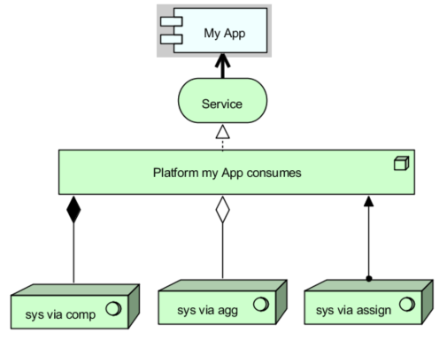
Or, simply through multiple entities providing ‘serving’, ‘realizing’, or ‘assignment’ relationships, as you have shown.
In my opinion the assignment relationship needs to be be used carefully, so that only one node or interface or super-node (which could be a collaboration) is ultimately assigned to provide a more abstract entity.
I prefer collaboration or aggregation for precision as it shows that neither entity can be relied on to independently provide the service.
In your diagram it is possible for either the Primary or Secondary VMWare cluster to realise the service, but not possible for Primary DC VMWare Cluster to function without both VMWare ESX v12.1 and VMWare Site Recover Mgr working in collaboration.
Archimate is all about what works and who the audience is and their level of skill in interpreting the diagram.
Hi. I wasnt paying too much attention to the stuff below the service tbh - and here “service is king” - just more trying (and testing) that the service approach allowed the derived relationship to still work with VP. I initially sketched the lower level with aggregation as thats more intuitive as you suggest (and I assume for your nested boxes you selected aggregate ?) but it stopped the derived rel’n showing up (just retested using composed, aggregated and assigned and only assign gives me the top to bottom traceability).
Enough sources suggested to me “assign” was a good equivalent to deploy either for an artefact if you do it that way, or system software if done that way. Seems like assign is a stronger rel type? Or its a bug in 15.2 - does aggregation work ok with 15.1 to get the derived rel’n?
Anyway good to see you are keeping the VP flame alive
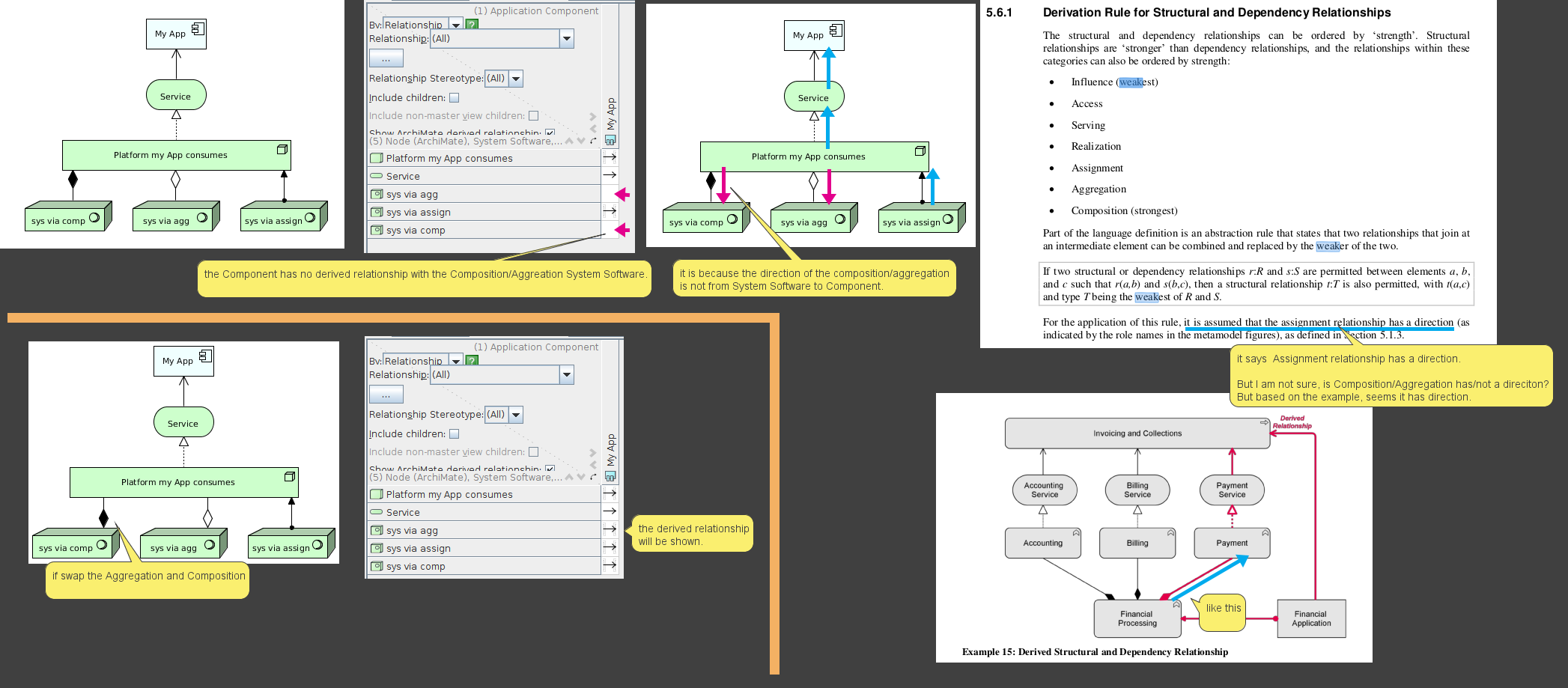
Hi, you are asking following 2 questions? 1. Why does not show stronger relationship type on derived relationship? 2. Why there is no derived relationship on your Aggregation/Composition?
Answers: 1. Based on spec, seems should show weakest, not strongest.
Hi peter. Re point 2, According to 10 2.3 of the spec ‘a node can be composed of system software’. Also for active structural elements, nesting means assignment according to 5.1.3. Hence I went with this as drawing with composition didnt work.
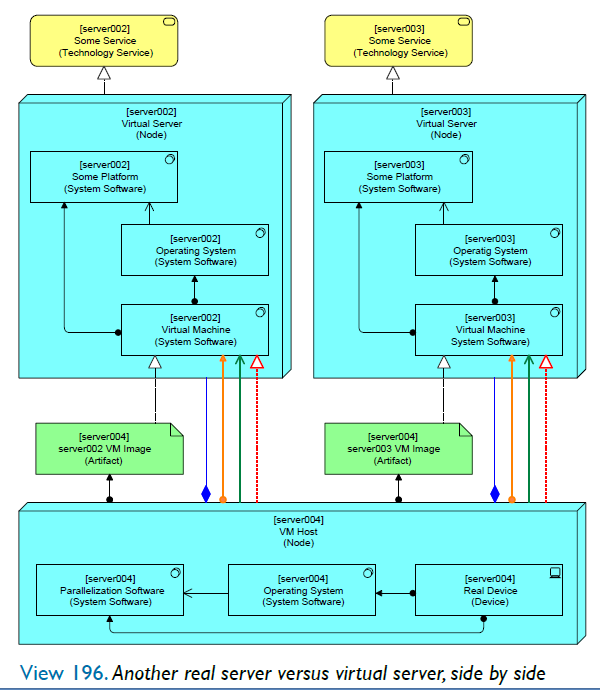
…and his narrative: The blue Composition relations and the route via the VM Image Artifact are equivalent to what has been used in View 194 [In this view…it is also not a bad choice to use Composition as the relation between the System Softwares of a virtual machine, as it mimics the structure of the Artifacts that Realize the System Software elements.].
The other alternatives shown are:
• The orange Assignment shows the relation between the active parallelization host element and the virtual device.
• The green Serving shows that the virtual device requires the parallelization host to function.
• The red Realization is derived from the route via the VM Image Artifact.
There are of course many, many more ways to model hosted virtual servers. There is a myriad of choices in what you show, leave out, etc. Here again, it becomes clear that you need to
find your own pattern based on what you like and need. A small reminder: this book is in the end about understanding the language and which options it gives you.
This seems consistent with Peter’s model where multiple virtual nodes compose the VM Host. However, as Steve points out, there needs to be a way to aggregate/compose system software and devices into a node, therefore the dependency model breaks when analysing dependencies on the consitituent components of a node.
This is a healthy debate. It helps to get a clearer understanding of Archimate and how VP implements it.
Correctness may be elusive in Archimate as there are many ways to interpret aggregation/composition relationships.
It is my understanding that Aggregation (and sometimes Composition) may be interpreted two ways. Either as a collection, or as an assembly.
If used as an assembly (as in your example 15 from Archimate spec), Financial Processing is the assembly of Accounting, Billing, and Payment functions. Financial Processing may exist without Accounting, but accounting could not be separated from Financial Processing.
If used as a collection, it may represent a notional superclass of entities, such as in my Windows Server 2012 R2 example shown below. Here each of the servers are aggregated by the collection. The collection and components can exist independently from each other. Server A may be upgraded to Windows Server 2016 and will therefore cease to be part of this collection.
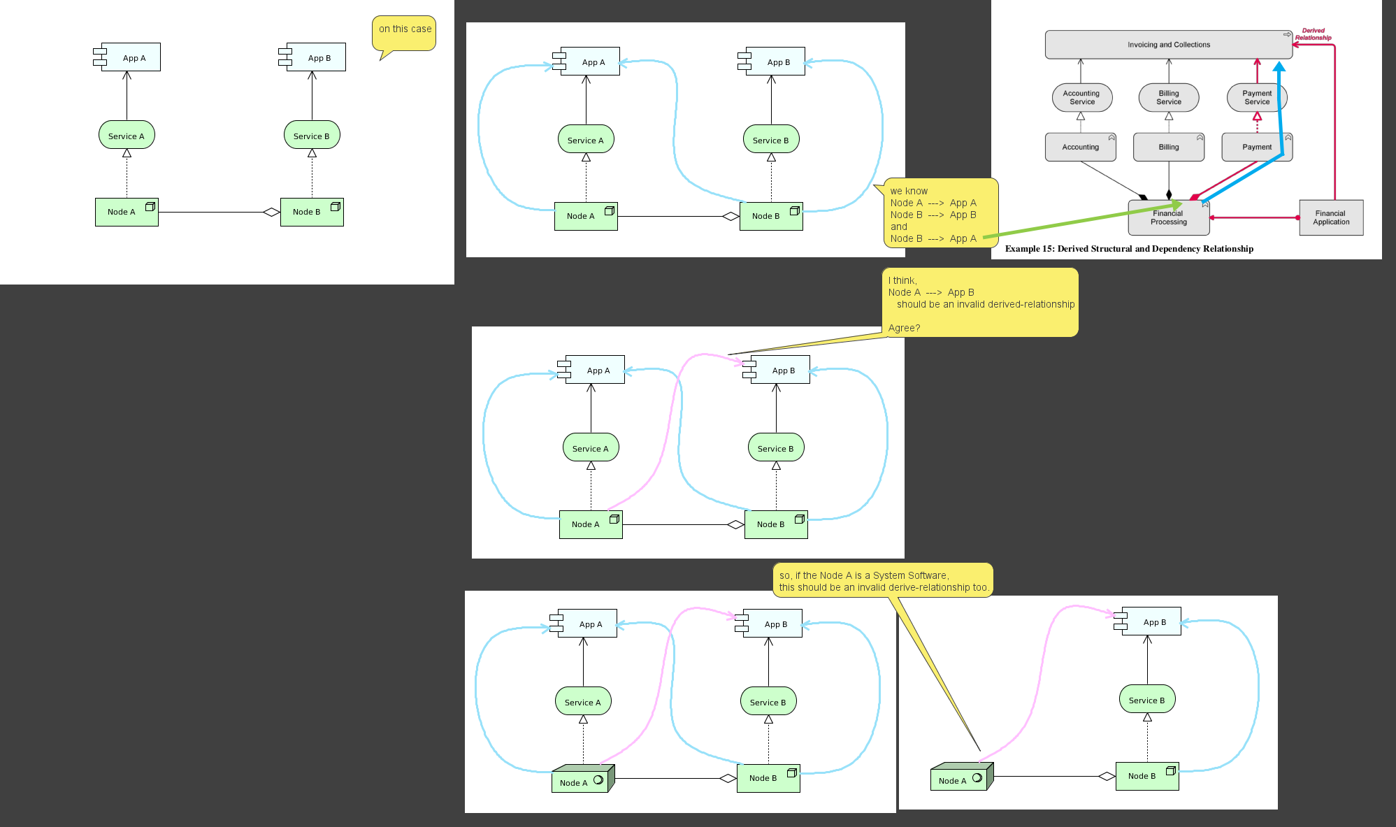
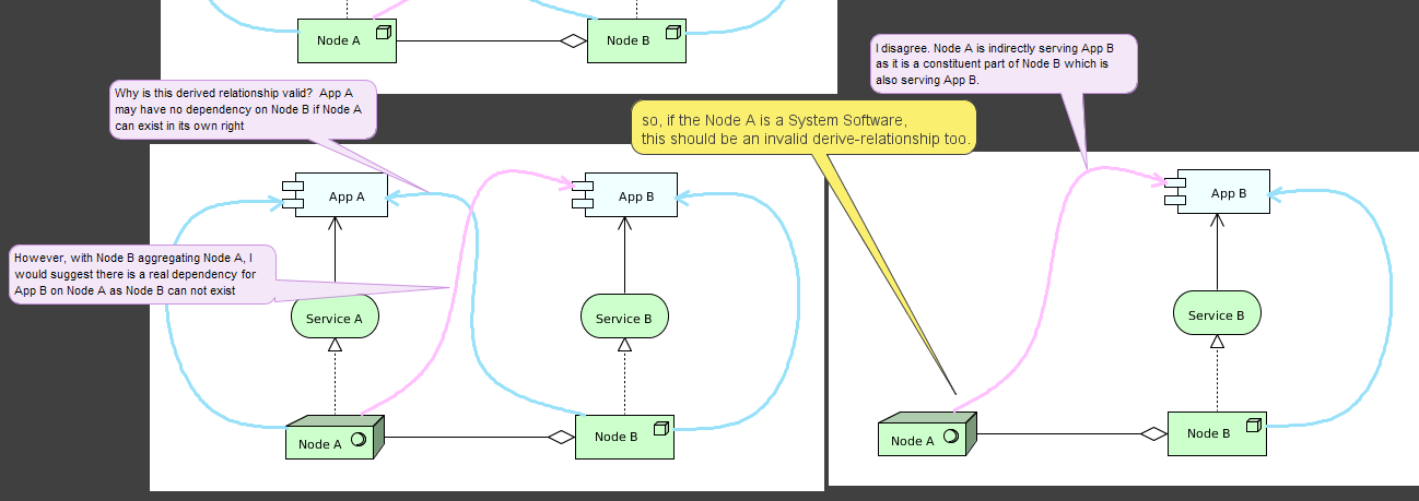
I think on your first diag, the Service becomes more important. In that case I would show Service B is served by Node A or perhaps if the Technology Service purpose is to be a “High Availability” layer then it would just be the one service serving both apps.
If there is a real dependency between the two Nodes, I think the aggregation is a less intuitive way to show this dependency (aggregation being a “may contain” rel type).
As drawn, the fact of the aggregation does imho create a derived relationship from App B to Node A (technically). I wouldn’t myself draw it this way because that it probably not what an infrastructure person would actually “mean” even if it correct archimate. Where the node is specialized to system s/w it is probably ok, but when it just represents a processing platform conceptually, it breaks down somewhat.
Id also say that Service A and Service B are likely the same service in this case (eg resilient database service?) - so if this were eg Oracle RAC Db the service is “one thing” from an app perspective looking down to the technology. Maybe the language of archimate does not permit a service to be served by more than one node? That said formally I guess one should be using tech interface but the diagrams simply get too messy. I note Gerbers diagram has service only being realised by one node, but in this case he has used node to represent a “physical” VM and hence that is true. If the node itself represented a part of a two node database cluster, then this would offer up a single “service” or interface that allows the application tier not to care that things are actually physically distributed across multiple nodes/machines and thus that service is probably realised by two interfaces.
But back to the core question, the derived relationship between nodes using aggregation would appear to be technically “true” but is likely not what the author “meant”.
Hi Chris. I’d say that once you are saying that server a is composed of windows server…server a, youre down at phycial and it becomes an artefact - a specific instance of software deployed onto a specific server. The server node should be a device in your case, and the sys s/w is then assigned - I suggest.
Ive used Node to represent eg “MyOrg Azure Tenancy” realising Queing, Authentication services etc, and then just used “lazy” nesting to show the system software services (Azure SQS, Azure AD etc) as ineffect an aggregation (cant be a composition imho as that would mean it belongs to the Tenancy node only).
Steve