I’m searching for some symbols in activity diagrams and can’t find them anywhere…
When calling an activity in an activity diagram there should be a little fork-symbol in the calling action to tell the reader of the diagram that an activity has been called. How do I create such a symbol?
Also in activity diagrams: It is possible to create guards on control flows. There should be the possibility to mark these guards as exception. I read in an UML-book that there should be a small triangle in front of the guard. How do I produce this?
#1 Could you please provide me with an image about the fork-symbol that you are talking about? I could not find an example from UML Specification.
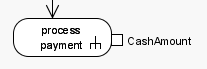
I have attached a small picture of an action calling an activity. I know about this kind of presentation from the standard books for UML 2.0 in Germany (“Die UML 2.0 Kurzreferenz für die Praxis” from Bernd Oestereich and other books). If there are books available in English, I do not know.
You should now see a small triangle appear next to the pin.
After following your instructions (defining a new parameter for a pin, enable Exception and so on…) I still cannot see any triangle, even when activating the Presentation Options “Show InStates” and “Show Constraints”.
What am I doing wrong?
I’m using Community Edition 5.0 Build 20050624u.
#1
I understand now. I just found from the UML Spec. a diagram of activity with rake-style symbol within the symbol. I have passed your enquiry on to our developers, and will get back to you as soon as I can.
#2
The steps you performed is correct, but the build you are using is quite old. Please install again the latest release. This should show the triangle symbol properly.
The model that support rake-style should be Action, not Activity. To show the rake symbol, right-click on an Action and select Open Specification… from the popup menu. Afterwards, set its type as ‘Call Behavior Action’, then assign it a behavior.
Usually we use activity diagrams to describe business processes (or business use cases). Before when we were designing in Rational Rose, we could relate the actions with business entities (objects in this case). I have several questions about it:
In that case, the relationships were dependent (dashed), but now the available relationship is an association (object flow). Some people use the generic conector and make it dashed. Using other relationship does not create a contradiction in what you want to represent? Also I do not understand why this differences exist, if it is the same modeling language, just change the tool.
Furthermore, to say that those were business entities, we used to define different stereotypes. Where I could get these stereotypes? Why are not defined by default?
I would be very greatful if I could find a example of a complete activity diagram, using all the elements of the notation (swimlanes, objects, synchrontization bar, decision nodes, etc.).