2 trivial questions. Didn’t think it worth raising a new topic for each.
1 Ctrl+Click to Open
Lets you go straight to a glossary item Great. But how do you we get back to where we clicked? In other words, what’s the equivalent of the “Back” button? I found a ref in another forum question which suggests the answer is alt-(left key) - which I assume means alt + (left cursor) but it doesn’t work.
So far, I’ve only been able to get back by going to the switch list or project browser and crawling back to the diagram from which I clicked
2 Arrowheads drawn by dragging the Resources Catalog - no match in the “Format Arrow Heads” dialog
If I use the “drag resource catalog” option, its a nice quick way to add new elements. They all get drawn with default connector and arrowhead.
If I need to insert a new element in the mix and connect to and from it with my own connectors, I cannot match the arrowheads drawn by the auto method.
and I’ll throw in two minor irritants.
2a Why doesn’t the connector logic follow the default rule that arrowheads will always appear at the destination? I always draw my connections from source to destination, yet about half the time, when I then add an arrowhead, its at the source end and I have to use the “reverse connector” option.
2b I think I spotted a reference, somewhere, to a “default connector” option but cannot retrace my steps. 99% of my connectors are straightforward “source to destination, with arrow at the destination”. Surely there’s a way to make that the default (like it is with the auto “drag resource catalog” behaviour)
The quickest way is to click on the main window (in order to move the focus away from the description) and then pressing control + tab. So keep control pressed and then press the tab key once. This allows you to move to another opened diagram, and by default it’ll point to the one you used last.
I can’t really answer that because I’m not a VP developer, but I do have a theory…
However, this heavily depends on the kind of diagram we’re using. But I think this is best noted with use case diagrams; especially when connecting 2 use cases.
So my theory is: Visual Paradigm always follows the flow of information, originating from the use case you selected. So everything you do will affect that particular use case:
Using an association: the flow goes from the original use case onto the new one. It more or less “leaves” the use case. Data must flow here.
Using an include: once again the flow goes from the original to the new one; the original functionality is being added to the another use case. So we’re more or less still working with the same function.
Using an extension… Now it’s in reverse (you can also see this by the direction in which the arrow points). That’s because our original use case is the basis (start) of the information flow, our actions affect that use case because that’s where we started.
And an extension doesn’t necessarily mean that all the functionality is being (re)used, only that it’s a possibility that (parts of) the functionality get (re)used. So if we were to extend on another use case we’d basically be suddenly working on a whole new function. Which is a bit illogical because we started our work with the first use case.
So when you drag a resource catalog from a model element then your actions will always directly affect that originating model element. Not necessarily another one.
Anyway, this is not the official explanation of course, but just my theory.
But always keep in mind that VP pretty strictly follows the specifications as they’re set out by the OMG group (depending on the diagram of course). Which is also where I based my theory on.
When you compare this behavior to the official specification then it really makes sense.
I hope I managed to explain that well enough… It’s a very abstract topic.
I’m impressed by your speculation on arrowhead direction but I think I’ve found a much simpler explanation by watching more carefully what I was doing.
Draw a connector between any two objects and, when you hover over it, you will see the “Format Arrow Head” option appear AT BOTH ENDS. (that’s the bit I hadn’t previously noticed) The arrow head will then appear at whichever end you select to perform the “format”! (and you can put one at both ends if that is appropriate.)
Quite neat actually. But I still want to able to set a default “connector with arrow moving from source to destination”
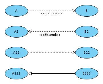
I always created the connection with the resource catalogue going from A to B. As you can see it goes from left to right when I add an include and dependency connection, but goes from right to left when you add an extension or generalization.
So what @HarryStottle is suggesting is to have an option which can define a default behavior here. So basically the option to tell VP that if you create a generalization then it should always target the end use case (B222 in my example).
Actually almost all the default connectors drawn in VP is from source to destination, and ShelLuser have already shown two of the very few exceptions - Generalization and Extend, there is Realization as well.
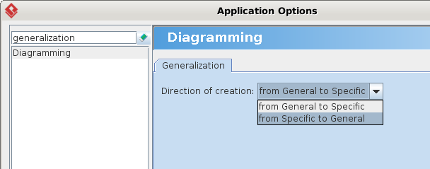
For Generalization, we’ve provided an option that can be configured in the Application Options dialog box, you can set it in Diagramming → Generalization → Direction of creation. By setting it to From Specific to General you get the same source → destination behavior. But currently only Generalization has this option.
For question 2, do you mean using the Format Arrow Head resource of the Generic Connector, you cannot make it match the appearance of the built-in connectors (e.g. Generalization, Containment)?
It is because in VP we support a wide variety of visual modeling notations, and the appearance of the built-in connectors, in term of line weight, dash patterns, arrow heads, are very specifically customized to the notations that they support. So it is not quite possible to provide all the same options for the Generic Connector.
And in fact Generic Connector is provided as a last resort when the standard built-in connectors cannot model what you want. It is always preferred to use the built-in ones because you can actually model the specific model element properties, some even visually presented in the diagram like Association’s aggregation kind or navigability. And you can take advantage of the connection rule validations which you cannot find using Generic Connector.
As for question 2 a) and b), I think you’ve figured out already that we allow configuring the arrow heads of the Generic Connector in both ends, right?
First off, my smartass guess that direction depended on which format option we select once the connector is in place was wrong. I tested it and still got the 50-50 behaviour.
Second, shelluser is correct in spelling out my suggestion more competently than I did.
Third, I’m intrigued/bemused by Antony’s reference to the generic connector being the last resort and that the other built in connectors included “generalisation” and “containment”
I didn’t have a clue what “containment” meant in the context of the diagrams so it never occurred to me to use it. I just tried and it’s not at all obvious how to use it. It draws lines between click points anywhere in the drawing but I couldn’t figure out how to stop it, other than by escaping, when it disappeared!
“generalisation” doesn’t appear on my tool list, at least, not in activity diagram mode.
what other “connector” options lie hidden among the tools?
Which reminds me of another query: I’m sure when I went through the tutorials, I saw a shortcut way of finding the tool you are looking for on the tool list. Can someone please remind me what that is, because I cannot retrace my steps!