Then welcome to the forums.
First things first though… Keep in mind that this forum is mostly aimed at providing support for Visual Paradigm, the software modeling environment. I’m not trying to imply that your question is out of place here (it’s not, but even if it was it’s not my call to make anyway) but because of this:
Thing is: when using VP then you don’t have to worry about official notations, let VP handle that for you  Most of all, official notations are mostly used in diagrams, and we’re not making one here. So just calling it by its name is good enough.
But back to your question:
[quote=78Star], and “PC controls”<>. they both have the same base use case listed bellow.
- Open Menu
- Rotate Character
- Activate entity
But Mobile Controls also has
- Reset Horizontal Rotation
Is there someway to represent a base system that both systems inherit from, and then have mobile controls extend it?[/quote]
Not with a Use case diagram, no. Keep in mind that a Use case diagram is only meant to display the actual functionality of your program and/or environment. Nothing more, it doesn’t bother itself with inner workings such as inheritance. Save that for a class diagram or maybe a deployment diagram.
A system encapsulation in a Use case doesn’t necessarily represent an actual system, it can just as easy be a boundary of some sorts which groups certain functionality together. Keep things simple and to the point so to speak.
I’d use 2 system boundaries: Controls and Mobile (maybe “mobile controls”) but that’s it.
Rule of thumb: Use case should be about (basic) functionality, and that’s it.
However… that’s talking about strict UML specification.
If you want to emphasize on the relationship between the two systems then you could consider adding a dependency arrow. It might make things more clear, but it would also invalidate your Use case where standards are concerned.
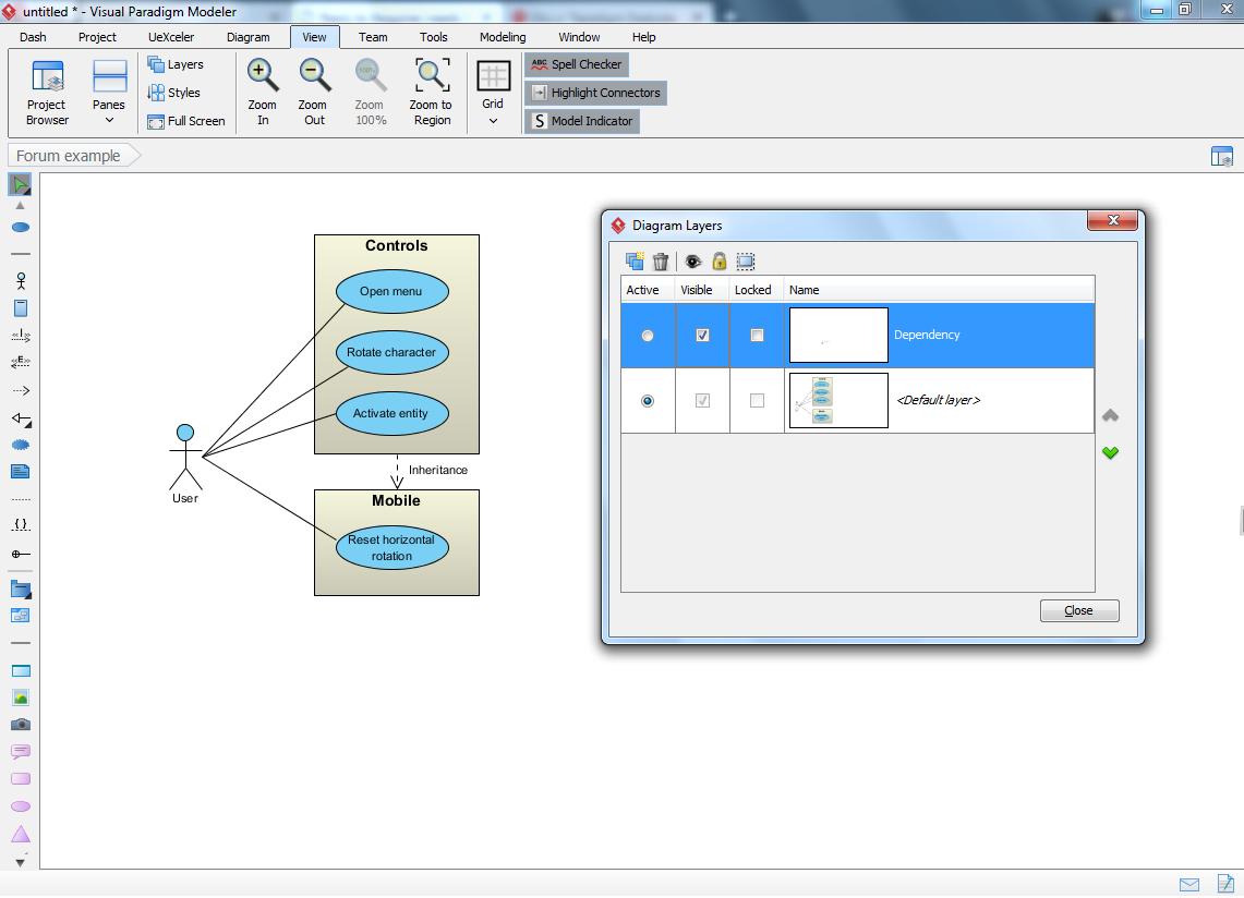
As such here’s what I’d do (talking VP usage here): Create a new layer (View tab => ‘layers’ option), call it “dependency”. Then draw a dependency line between the two systems and optionally label it “inheritance”. As said: this will invalidate your diagram where UML standards are concerned.
So here comes the cool part: if you want to show the relationship between the systems then leave things as is. If you need to provide a diagram which is compliant with the UML specification then simply hide the “dependency” layer. I’ll attach an image which showcases this.
I realize I may sound like a marketing drone right now (I’m not, I’m an enthusiastic fan) but that diagram took me 1 minute or so
[quote=78Star]Question2: The tutorial I am taking says the use case shouldn’t specify the how things are done, but should I specify difference, for example.
vs
-Rotate with mouse?[/quote]
No.
Use case is all about functionality and nothing more. So “rotate character” it is, nothing else.
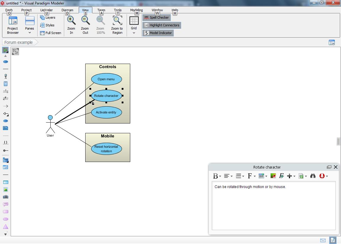
Of course (here I go again :mrgreen: ) VP has ways to showcase this while still honoring the UML standards. I’d use the ‘description’ function in VP for this. It allows you to provide (“attach”) additional information to your model elements and its existence will be displayed through a small indicator.
See 2nd attachment: the small page icon/indicator in the lower left corner shows you that extra information has been provided. Ignore the black “square dots” around the use case, that’s only showing because I selected it.
Hope this helped.
use_case_forum.jpg
description_example.jpg