The unofficial "share your tips" thread!

Hi gang!

Now that we have this awesome community forum which allows us, the Visual Paradigm Community, to more easily discus all sorts of things I figured we might want to add a general tips and tricks thread. Visual Paradigm (the software) is an extremely versatile program and it has so many options that I think it’s quite easy to overlook something.!

So what better way than to share some of our discoveries?

Free online training!

The Visual Paradigm team has made an official online training which consists of 27 lectures which will show you pretty much everything there is to know about VP. It introduces you to the software, the several supported modeling languages (introduction to UML, BPMN and UeXceler) , how to share your projects with others (using VPository) and it also explains some more advanced topics such as document generation, the model repository and how to export and print diagrams.

And more: there’s also a tutorial available which explains database design & management and a tutorial which explains Agile development using UeXceler.

See here: FREE Visual Paradigm Training - Visual Paradigm Essential

Trust me: even if you’re already well familiar with Visual Paradigm it might still be useful (and fun!) to go over some of these chapters.

Community Circle

I actually overlooked this at first! :blush:

If you start Visual Paradigm and look into the Project tab you’ll notice an icon called Community Circle (see screenshot above). This gives you access to a huge collection of examples which can showcase nearly every available diagram type. From UML to BPMN right down to Mind mapping, Cause and Effect and Fact models.

And the best part? As its name suggests this is mostly maintained by us, the Visual Paradigm Community. Do you have a project which you think could be useful for others as an example? Then consider sharing that so that others might learn from it as well.

And it gets better: even if your license does not give you access to a certain diagram type then this won’t stop you from viewing an example in read-only mode.

Panes from the past

Although the project browser is a really good way to get an overview of all your diagrams and their associated diagram models, sometimes you might prefer to have somewhat more direct access. Something which doesn’t require you to switch to a different window all the time.

Well, exactly that’s what the panes section is for!

As seen above you’ll find the panes option in the View tab. This button gives you access to 8 panes in total:

  • Diagram Navigator - Shows an overview of all your diagrams (shown above).
  • Model explorer - Shows an overview of all your model elements.
  • Class repository - Shows an overview of all your class diagrams.
  • Logical view - Allows you to categorize your diagrams.
    ** Note that this pane is superseded by both the ‘model structure’ and ‘files’ sections in the Project browser.
  • ORM - Gives you an overview of your ORM diagrams.
  • Stencil - Provides access to a large collection of shapes and icons which you can use in your own diagrams.
  • Property - Shows the properties of the currently selected model element. This is comparable to the information in the specification window (press enter when a model element is selected).
  • Message - Opens the message pane, you can also click the message icon in the lower right corner. This shows you all the current application messages.

Fun fact: These panes date from the time when Visual Paradigm didn’t have the sleek interface yet.

And there you have it!

Three tips which will hopefully be useful to some of you out there. I’ll be adding some more at a later time.

1 Like

Thank you for sharing such a informative post in Tips and related resources. This Forum definitely a good source for ideas and help for Visual Paradigm :smiley:

1 Like

Hi gang!

Well, its been a week and I did promise to share some more tips later on. It really helps that I learned a few things about this forum in the mean time, so lets jump right in!

Dash menu

I honestly just started using this myself for a week or so, and it is so easy to miss yet can save you so much time…

If you’re using Visual Paradigm’s sleek interface then you’re using a so called “Ribbon-like interface”. On the top of the screen you’ll find several tabs which open different toolbars which contain different options grouped together by their relevance.

For example: the diagram tab contains options such as copy / paste, group options, search… All sorts of options which can be used to manage your diagrams. The Project tab on the other hand contains options such as load and save project, import / export, print, and so on. All sorts of options which apply to an entire project.

Although this makes it quite easy to quickly find the option(s) you need, it also means that you may be switching back and forth between tabs quite a lot. Although Visual Paradigm provides easy to use keyboard shortcuts (see above) it could be much easier if you didn’t have to switch between tabs in the first place.

This is where the Dash menu comes into play…

How to start using it

It couldn’t be easier! Just use Visual Paradigm as you normally would but every time you find yourself using an option more than a few times try right clicking on it, and then select “Add to Dash Menu”. Continue doing this until you’re satisfied, once you’re done open the Dash menu (click on the first tab).

Now, things probably look pretty chaotic right now so start by right clicking on the dash menu and then select the option “Configure Dash menu…”. This will open up the following window:

You can drag items left and right across the menu to reposition them, you can place items next to each other which makes VP use a regular icon, but you can also group items so that you create a stack; you can place a maximum of 3 options above each other which can save up a lot of space.

Finally also take note of the separator item; this allows you to add a small space between icons which can help you group those together. Despite what I showed above you don’t need to use separators if you stacked some options.

As I mentioned before I only started using this quite recently, but despite that I still noticed that I’ve been switching between tabs a lot less often. Instead I simply click the option(s) which I need and then I can continue to focus on my work again.

Working with multiple diagrams => Subs & Refs

When you’re working on a more complex project then you may find yourself using several diagrams which each visualize a different aspect of your work. Some diagrams even provide native support for referencing other diagrams, this is particularly true for the UML Activity and the BPMN diagrams.

And as one could expect Visual Paradigm itself can also help you with this. However, as usual this isn’t a “One size fits all” kind of feature and you might want to take note of both ways to do this in order to decide which option meets your requirements the best.

Sub diagrams

Here I have diagram which shows an overview of all the different UML diagrams. If you take a closer look at the sequence diagram entry you’ll notice that it has a small icon in the lower right corner. This indicates that this model element has a so called sub diagram assigned to it. Clicking on the icon will show a menu which lists all the linked diagrams and will also allow you to add even more sub-diagrams.

This option can be extremely useful if you have a model element which roughly describes a part of your workflow which you also want to describe in more detail. Instead of cluttering up your current diagram you simply assign a new diagram to the model element which you can then use to showcase all the missing details.

So far, so good. However, there’s something you need to be aware of…

If you’re using a specific project model structure then any used sub diagrams will also have their affect on this. Lets look at the model structure for the UML overview diagram which I displayed above:

The diagram itself is listed under the “Website” model, and I’ve selected the “Sequence diagram” model element. But if you look closely you’ll notice that the “Sequence example” diagram is shown here as well.

That’s because “Sequence example” is a (sub) diagram which is ‘linked’ to the “Sequence diagram” model element. In this case that is exactly what I intended; this helps me to not only keep track of all my website related work, but it also shows me the underlying relation between the different parts. In this particular example the relationship between the “Sequence diagram” model element and the “Sequence example” (sub)diagram.

Unfortunately this can also create a problem.

What would happen if I needed to refer to a diagram which was part of another model? For example: let’s say that I have another sequence diagram in my “Examples” model and I want to refer to that as well. Well… the very moment when I select that other diagram to be a sub-diagram then it will be automatically moved to the “Website” model in order to reflect on the new relationship, just as you’ve seen above.

But now this creates a problem for me because I need the diagram to remain a part of the “Examples” model. That model should contain all of the examples in my project.

Fortunately there’s a solution…

References

Instead of adding a sub diagram you can also add a reference. If you scroll back to the UML overview diagram shown above and look at the “Use case diagram” model element you’ll notice that it has a small icon in the lower left corner. That icon shows that the model element contains a so called reference.

A reference is just what its name implies: a pointer to something else, where ‘something’ can be just about anything: another diagram (in the same or another VP project), a file, an URL, a folder, or even another model element or a shape can be referenced.

This allows you to still have direct access to another diagram yet without having to move that to a model in which it might be out of place.

Adding a sub-diagram or reference

Just in case that it wasn’t clear enough: you can add a sub-diagram or reference in the same way as you follow up on one. Just click on the model element and the icons will automatically show. Click on the icon you need and then select the “Add sub-diagram” or “Add reference” option respectfully.

Locking your diagram

And finally…

Has this ever happened to you? You finished a diagram after a few hours and made sure that all your model elements are perfectly aligned to each other. Now you’re using this diagram as an easy reference.

While working on your project someone asks you something about it and you quickly open the diagram but unfortunately move one of your elements by accident. Because you’re busy talking about the project you forget all about this accidental move.

… only to get reminded about it after you closed and saved your project. “Oops” :scream:

Fortunately there’s a solution to prevent this from happening: Locking your diagram:

It couldn’t be easier: just right click somewhere in your diagram and find the option shown above. Once clicked you have several ways to protect your work from tampering. First you can add a simple lock, this will trigger a warning whenever someone (or you) tries to change the current diagram. A simple hit on the escape key will be enough to dismiss the warning and undo any accidental changes.

Next you can also add a password; this will seriously help you protect your work because no one will be able to make any changes without your authorization.

Better yet: if you’re working in a team you can also chose to assign specific team members. This will allow the members to work on the diagram while everyone else will be prompted about the current lock, optionally with the requirement to enter a password in order to unlock it.

Small changes?

locked_warning

So what if you have any quick changes you need to make? Well, fortunately you don’t have to remove and re-apply the whole lock again. Just click “Unlock” in the pop up window (as shown above) and that will grant you temporary access. So during your current session you can apply changes to the diagram, and once closed it will be locked again.

And there you have it…

Three more tips which can hopefully help you get even more out of Visual Paradigm.

1 Like

So last week I addressed some very specific topics which have been a bit (too?) complex. I can well imagine that not everyone uses a model structure for example. So today I want to focus on some more general features.

Stencils

I assume we all know about Microsoft Visio? If not: it’s a diagramming application which is part of Microsoft’s Office suite. It supports several modeling languages and standards, as well as so called stencils, Microsoft often puts a lot of attention to that. A stencil is basically a small graphic (or pictogram if you will) which you can use in your diagrams, either to illustrate something or to use it as an actual element.

So guess what?

Not only does Visual Paradigm fully support stencils (and the option to import Visio stencils) it also provides you with some stencils right out of the box, as shown above. All you need is the Stencil pane; and I explained panes in more detail in a previous post (see above).

I know I sometimes sound like a fanboy (trust me on that) but even with all bias cast aside I can still honestly say that I’m quite convinced that Visual Paradigm may very well surprise you here. If you’re focused on some of the things you can do with Visio… well… look at my screenshot above. And that was ‘only’ made with a Modeler license (the lowest tier of licenses so to speak). Now try to imagine what you could do if you were to combine this with more high-end diagrams (mind mapping, impact analysis and the project management tools spring to mind).

And… All this while using VP’s highly acclaimed resource catalog feature which lets you concentrate on your diagrams instead of having to drag everything from a palette from the side (note: this does not apply to the stencil models, but it does for the rest of your diagram).

Layers

So take the diagram above. The bottom part is a by the book UML deployment diagram, but the use of stencils obviously invalidates the official standards. If your boss asked you for an UML diagram then I’m pretty sure that the above would be shot down.

But what if your clients would seriously appreciate a “hands down” kind of diagram as shown above and you just can’t convince your manager that strict standards aren’t everything?

VP has you covered: Layers.

vp_layers

Go to the ‘View’ tab and find the ‘Layers’ option. Once clicked you’ll see something as shown above. Here I simply made a new layer, I selected all my stencil elements by dragging a selection box, right clicked and then selected the “Stencils” layer in my pop-up menu.

So what does this do? Easy! The moment my boss asks me for my deployment diagram I call up my diagram, hide my stencils, and print (or export) the diagram. Fully UML 2.5 compliant.

Then when my clients visit I simply do the same thing, make the stencil label visible and then use that for my presentation.

2 different audiences, 2 different layers and one (awesome) diagramming software.

Automated backups

Above shows a project which I’m currently very busy working on, and as you can see the folder not only shows several .bak files, they also show you how old every copy is.

Now, I’ll be honest here: I tried looking up a way to turn this off because I always try to cover all bases, yet I couldn’t find this part (even though I’m convinced this is (or was) a supported feature, if I find out more I’ll send an update).

But if you keep the average size of a VP project in mind (pretty small) then I also think the optional overhead seriously outweighs the provided safety. As you can see above I can even go back pretty much 1 whole month into my project history if I need to. And this is localized stuff, if you’re using VPository (which I can seriously recommend) then you’re even better covered (because of all the revisions, I think I’ll do a post on VPository next week, it deserves a spotlight!).

So yeah… if you messed up your project somehow then look into your workspace: chances are high that you’ll find backup copies.

So how do you use this?

You will need to use a file manager to go to your VP workspace, then rename the entry you want to use; just ensure they get the .vpp extension. Then select ‘open project’ in Visual Paradigm, find the renamed file (you might want to copy this to an easily accessible location) and then just open it from there.

Even when all else might seem to fail VP still tries to keep your data safe.

Honestly: it’s one of the many VP features which I seriously appreciate, it’s one of those features you’ll probably never realize is there until you suddenly need it.

In conclusion

I hope this was useful for some of you, next week we’re going to take a closer look at VPository. If you can’t wait for that just visit VPository.com. Registration is free (you can also log in with a Google account) and I think you may be surprised to discover the kind of things you can do there.

1 Like

Visual Paradigm 14.2 got released last week and if you’re curious to see what’s new then just follow this link. It’s also one of the reasons why my post got a bit delayed this week; I was curious about the new environment so spend time looking around rather than writing.

Now, last week I said that I wanted to do a VPository special, and that’s still a thing, but because 14.2 got released I also want to include that. So here goes :wink:

Using enter key to open Use Case specification

I’m obviously biased here because it was my suggestion which triggered this functionality to be implemented. The option works like a charm, but it could be a little tricky to set it up, so I figured I’d share…

What does this do?

As you may know you can press the enter key whenever you have a model element selected and then it will open the specification window. There you get a full overview of all the properties of the model element; you can change things such as its name, the ID, its visibility but also settings which are specific for the model element you’re editing. With a BPMN task you’ll find a Procedures tab whereas you’ll see things like Goals when editing an actor element.

So far, so good. But if you try this on a Use Case then VP will behave different by default. Instead of opening the specification windows you’ll open the Use Case details. This is basically a specific VP feature where you get to assign a lot of extra information to the use case model. The only problem is that this functionality is only usable with a Professional license or higher. Therefor users who have a Standard or lower license might have more use for the specification window instead of the Use Case details.

Well, in 14.2 we can set this up!

How to re-assign the enter key in Use Case

This got me seriously confused at first… The trick is not to try and instead (re)assign the enter key but to assign a new (different) key to the “Open Use Case Details” function. By default it has no key assigned to it, which means that it’ll use the default behavior (which is what I described above).

So here’s how to set it up:

  • Go to the ‘Window’ tab and click the option “Application options”.
  • In the new window select the ‘Keys’ section.
  • On the right you’ll see the full list of key assignments, and there’s a search bar on top. Use the search bar to enter: “Use Case De” (without the quotes).
  • Click on the ‘Use Case Details’ option, then click on the ‘Binding’ option below. Once selected press your preferred keyboard combination.
    ** My personal preference is to use Ctrl+U for this.
  • When done click ‘Ok’ and then restart the application.

After these steps you should now be able to press the enter key with a Use Case model element selected after which it should open the specification window instead of the Use Case details.

Keep in mind that you can assign key combinations to most of VP’s functions, so you might want to browse through the list.

VPository

What do Google, Microsoft and Visual Paradigm have in common? :thinking:

All three companies provide a collection of web based applications which you can use for all sorts of purposes. Google for example provides GMail and Google Docs whereas Microsoft has Outlook online and their online Office applications. Now, obviously I’m not going to talk about these two but Visual Paradigm instead. VP provides us with VPository which is somewhat of a web-based modeling tool but there’s much more to it. What I personally seriously enjoy about VPository is that it can dramatically enhance the functionality of your local VP environment. But lets not get ahead of ourselves…

So… what is VPository?

VPository can be many things, in no specific order:

  • Your personal cloud backup storage for all your VP projects (and optional related files).
  • An online project repository / version control system which allows you to keep track of all your changes.
  • A collaboration tool which provides the option to securely share your projects with others (PostMania).
  • A web-based online modeling tool where you can make a large variety of diagrams outside of VP (such as ArchiMate, several UML diagrams, Flowchart, PERT chart and even diagrams to visualize your AWS or Azure architecture).
  • A task manager (Tasifier) allowing you to set up activities, todo lists, group tasks or set up tasks for groups (a little pun intended, but I’m serious) and you can also discuss the whole thing amongst yourselves.
  • A complete, Agile driven, online project management system through UeXceler.

Can it get any better than this? Yes it can! :star_struck:

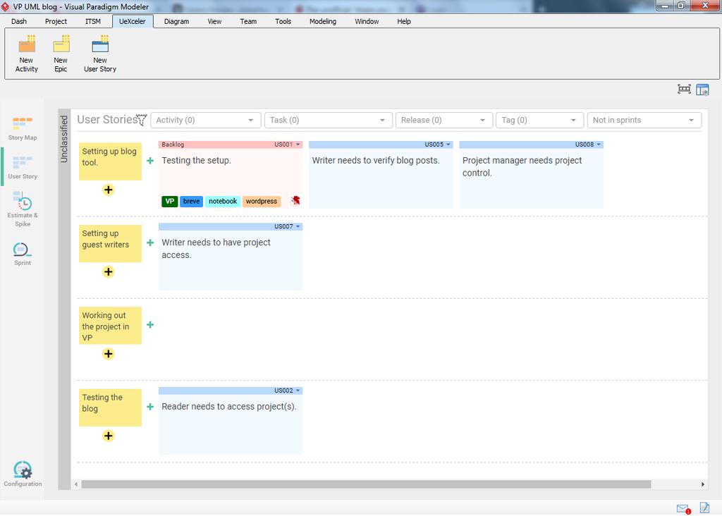
This screenshot was made within VP - Modeler edition. Ergo: VPository gives you project management capabilities, hosted in the cloud (so all you have to do is invite more people) and you can also use all of this within the Visual Paradigm program itself. Which I think makes the whole thing a lot more accessible in comparison to being limited to browser access only.

Also; if you’re using VPository with a certain version of Visual Paradigm (14.0 or 14.1 for example) then you don’t have to worry that your VPository will suddenly be automatically upgraded to the latest official release after which it might become useless to you or one of your team members. You’re in full control over that.

How (and where) to start?

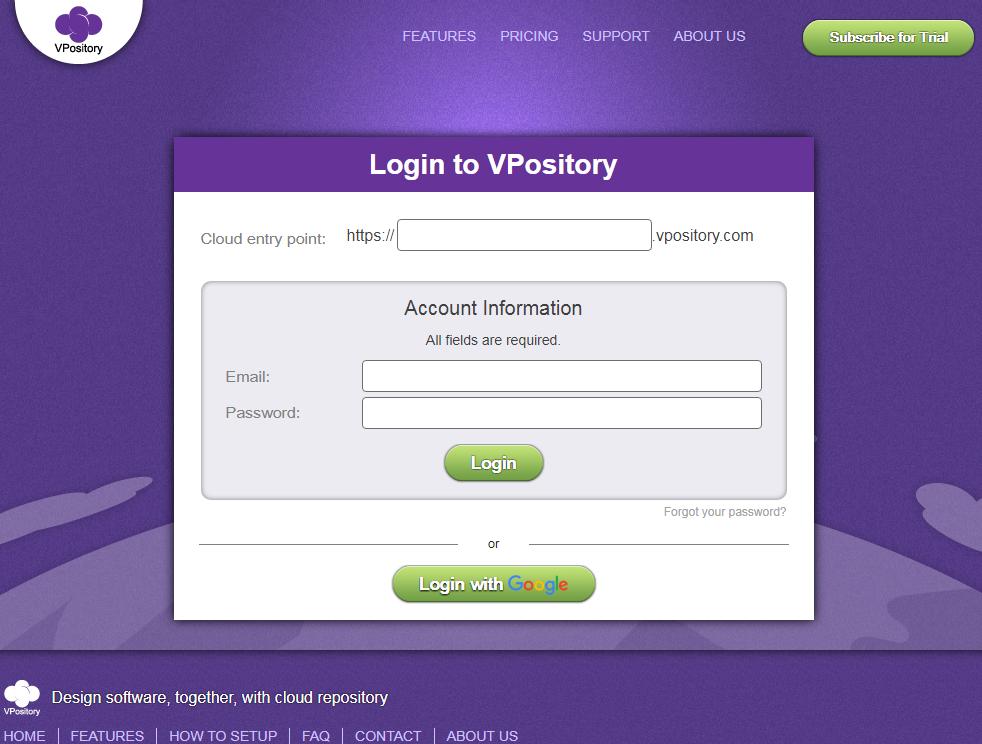
The first thing you’re going to need is a VPository account. Just head over to the VPository website where you can register and claim your own VPository environment. You can also open the ‘Team’ tab and find the option “Select Repository”, this will present you with the option to either register a new account or log on with an existing one.

Next you’ll need to start a new project. This can be done from the online VPository project management screen, but it’s probably much more useful to set this up from within Visual Paradigm. Start by logging into your VPository using either the Teamwork client (see the Team tab) or by clicking the “Login” option on the welcome screen.

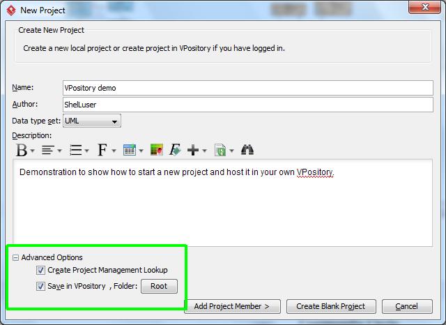
Once logged in you can then start a new project and expand the advanced options section which you can find at the lower left corner. This allows you to specify that you want your project to be managed within VPository and also select the location where to save it (usually the root folder is good enough, but if you need to you can also set up a specific hierarchy).

vp_start

When done you can just continue working on your project as you’d normally would. After you close VP it will remind you to both save and commit the project to VPository. You can comment on your changes and that will be logged in the project.

Specific differences

The main differences between using a local project and one hosted in VPository is that the latter allows for a lot of extra functionality. I already briefly showcased the UeXceler option above, but you’ll also have the Tasifier and PostMania options at your disposal.

So basically you’re using specific web interfaces but all within the comfort of your local VP environment. Of course one caveat is that in order to use online services you’ll have to be online. And that could be a problem in some cases. But even that scenario has been accounted for by Visual Paradigm

If you’d like to learn more about using UeXceler then I can seriously recommend to follow this free Visual Paradigm online training course: Agile Development with UeXceler.

Using a local ‘mini VPository’

If for some reason you can’t use VP’s online services but would still like to use a version control system then you can. Find the option “Select Repository” in the team tab after which the following window will show:

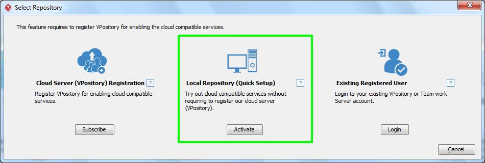
Activating this option will roughly provide the same functionality as VPository when it comes to keeping backup copies of your commits, allowing you to (visually) check your projects history and of course to revert changes and go back to previous versions.

Of course you won’t have access to specific features such as Tasifier or UeXceler.

And there you go…

Although I realize that I might have been describing some obvious features I still hope this can be useful for some of you. I’ve been testing out VPository quite extensively and recently also started using it for a more serious project and I have to say that I’ve been very impressed with the whole thing so far. As such I felt like sharing :wink:

2 Likes

Another week, another set of tips!

IDE Integration

Last weekend I had a somewhat interesting discussion online about modeling language editors and when I commented on how my preferred tool of choice (guess :wink: ) allowed me to focus on my work through use of the Textual Analysis and the IDE Integration some people within the thread were seriously surprised. So I figured that this particular aspect could use some extra attention.

In case you didn’t realize (or if you’re new): Visual Paradigm allows you to ‘attach’ itself to some of the most commonly used developer IDE’s out there. If you happen to program in NetBeans, Eclipse, IntelliJ or even Visual Studio then you might want to look into the IDE integration option. You can find that option in the ‘Window’ tab.

What this does is it’ll make VP embed itself inside your IDE, but in a very smart way. When you start your IDE you don’t have to worry about even longer loading times because of the VP integration, normally VP remains fully dormant. You won’t even notice that its there, this allows you to keep focusing on your work during the times when you don’t need VP support.

But the moment when you do you can right click on your project where you’ll usually find an option to load Visual Paradigm. Click the option and after a short moment Visual Paradigm will start. Now you do have to wait a little moment :wink:

When done you should soon see new panes appear, after which you’ll have full access to your VP project, but entirely from within your favorite IDE. Better yet: your Visual Paradigm project will be fully embedded in the project you’re currently working on, which also allows you to share it with others as well (using a version control system for example, provided of course that your IDE supports that).

In the screenshot above you can see me working within my favorite Java IDE NetBeans, here I finished working on a VP plugin project and combined my three diagrams into one overview diagram.

The Project browser’s Model structure tab

A modeling language can be used in many ways. Traditionally many people use such models to visualize existing situations, so the model is a means to showcase an environment or process and to relay the information about it to others. But if you have a tool such as Visual Paradigm at your disposal you can do so much more…

Why not use specific diagram types to brainstorm about certain ideas? A Use Case diagram for example can be an excellent way to start the plan for a design. After all: you can fully concentrate on the underlying functionality without having to worry (yet!) about the actual realization.

But… there could be a problem…

Here you see the diagram overview of a project I’m currently working on. Question: can you determine which diagram(s) are ‘real’ (so: showcasing an actual realized implementation) and which were only meant as either an example or analysis?

Don’t worry if you can’t because I can’t either, and I’m the one who made those :wink:

I don’t recall because I don’t have to, I let VP worry about that for me. How did I do that? Simple: by using a so called model structure:

Here you see the same project as before, but this time from within the model structure pane. As you can see I use 3 main models:

  • The Analysis model contains my brainstorming, rough (starting) ideas I had about this project. In this particular case that model consists of a textual analysis and a (still to be finished) BPMN diagram which will eventually showcase the entire game level which we’re making.
  • The Design model, also shown in the screenshot, contains ideas for the actual design. These aren’t necessarily perfectly working designs, but still working ideas which were eventually used in the actual implementation (either fully or partially). You can consider this section the beta stage of the project.
  • And finally the Implementation model; this section contains the overview of the actually working and implemented designs. This showcases how the project has been currently implemented and how it works.

So basically… Even though I have 2 use cases and 3 activity diagrams I don’t have to wonder what each diagram represents, because the model its in describes that for me. This is how I usually keep an overview over my larger projects and diagrams, and it’s a methodology which I can seriously recommend to consider.

How to use this? Easy: right click, and select the option to add a new model. VIsual Paradigm will make this really easy on you and provides the models shown above by default. Of course you can also add your own model names if you want to.

Diagram Info

Have you ever made technical drawings? If so then you probably have seen this concept before, and if you didn’t know already Visual Paradigm supports this feature as well. I think it really helps to make your diagrams look much more professional:

In case you’re wondering: I’m referring to the table in the lower right corner of the screenshot. It shows you the diagram title as well as a short description, this is the same information which you can add or edit in the diagram specifications (right click somewhere in your diagram, then select the “Open Specification” option).

Adding this is quite easy, but I can well imagine that some of you might overlook this option. When working on a diagram scroll down your palette. You will find the ‘Diagram Info’ option in the ‘Common’ category, which is usually listed right below the category which is relevant to the diagram you’re working on (Activity, Use Case, Class, etc.).

Easily overlooked, but I think it can have quite a positive impact.

And there you have it…

Three more tips which are hopefully useful for some of you out there.

1 Like

Hi,
Thanks for your sharing, but I’d like to make a correction:
Integration is available in all editions of Visual Paradigm and all (Community, Professional, Enterprise) editions of Visual Studio (except the old Visual Studio Express).

1 Like

Thanks a lot for the heads up, changed. And you’re right; I know it didn’t work with VS. Express (the at that time community / free version) and overlooked the docs. which no longer specifically mentioned the need for a license. I’m still using VS2012 myself so couldn’t try out that part.

1 Like

I guess it’s not much of a secret that I really enjoy working with the Visual Paradigm program. One of the reasons for that is because VP doesn’t try to force you into one specific way of working.

For example, lets briefly look at how you’d start a new project… There are multiple ways to do this. I personally prefer to either use a textual analysis diagram and then extract my information from there, but sometimes I also start with a Use Case diagram and then slowly expand on that (using sub diagrams for some use cases for example). But I also know of people who start with a BPMN diagram, and then fill in more details later on.

And this way of working manifests itself throughout the entire program. A few examples…

Bookmarks

In a previous post I mentioned the model structure and how you could use this to separate your diagrams. So what if you don’t want to use that? Maybe you find the project browser very distracting and would prefer to stay within your diagram.

The bookmarks option can do exactly that:

This option allows you to create bookmarks which can point to whole diagrams or specific model elements within the diagram. Better yet: you can also organize your bookmarks and separate them into different folders, somewhat comparable to the model structure mentioned earlier.

When you have your bookmark structure set up you can then use this to quickly switch between diagrams, and without having to use the project browser. I seldomly use this option myself, but it could definitely be useful, especially when you’re working on larger projects.

Jump!

Did you know that a Visual Paradigm project is basically a database in itself which contains all the information you put into it? As a result it also allows you to quickly access all the different items of your project, and the ‘jump’ option makes good use of this:

Even though this option is listed on the toolbar you actually don’t need to click that. Just use the control-shift-j or control-shift-d keyboard combinations to pull up this option. As its name implies it allows you to quickly jump to another diagram (or diagram element) by merely typing in its name. And as can be seen in the screenshot it also supports auto completion, so you don’t have to worry about having to memorize every detail in your diagram :wink:

Files tab: add supporting files to your project

As mentioned above I’m a big fan of the project browser because it really helps me to keep an overview of my project, even if the project becomes a little more complex.

But did you know that you can also add external files to your project? Files which probably have no meaning at all for Visual Paradigm itself but more so for you, or maybe your team?

Now, I’m usually showing example screenshots from a project which I specifically made for testing and review purposes, but this example comes from a real project I’m currently working on:

I have added some screenshots, specific function code and even some so called “structure files” (as seen in the screenshot). Now, if you’re working on a local project then this probably won’t be too much useful because all which basically happens is that your file(s) get copied to the project structure.

But it becomes a completely different story when you’re using VPository (as highlighted in a previous post). Because now all those files will also get uploaded onto VPository which means that they can also be made available to other users.

At the very least you’ll have a backup copy of your file(s) within the VPository cloud. So when something bad happens you’d still have access to your files.

And there you go :wink:

3 more tips which can hopefully help some of you out there.

1 Like

I’ve got some very nice positive feedback about my activities on the forums in the past days and that really motivates me, it’s always nice to learn that some of the things you do are appreciated by others. So thank you for that!

Now, this weeks post is going to be a little bit different :wink: This is a ‘share your tips’ thread after all and today I’d also like to share some other kinds of tips.

Know how

When I need to know something about Visual Paradigm then these forums are the first place I turn to, next to the official manual. This may even apply to you, random reader. But did you know that the Visual Paradigm team also maintains a ‘Know how’ section, a bit comparable to a blog?

It is somewhat easy to overlook I think but if you’re interested in learning more about Visual Paradigm then you should definitely check this out as well, VP shares some very interesting and diverse information there. From helping us getting started with the Visual Paradigm OpenAPI right down to giving us some clarification on how the licensing scheme works.

Better yet: if an article isn’t fully clear to you then all you need to do is ask in the comments, and they’ll get back to you in no time.

Web diagrams

If you’re familiar with VPository then you may already know about this: you can use the VPository website to create online diagrams. VP has explained this concept a few times already on their Youtube channel, something which I think is also really worth checking out. You may even learn something new there.

I’ll be very honest: some of the older video’s can be a little… “peculiar” (weird background music for example) but their latest videos are definitely worth it. Very good stuff.

Know what?

(sorry, I’m also playing with the forum features a bit :wink: )

Now, I think this is a very nice video. And as you can see: #2 online drawing tools…

But there can be so much more to those diagrams!

Please note: the following is staged (I kind of borrowed a friend and their account) but we do think it can make an interesting showcase.

So… my project resides in my VPository and I just added a new use case called “share information”. But how should I share this? So I decided to use PostMania and ask my friend AyanamiKun for feedback, you can see the conversation in the screenshot.

Due to reasons not shared because it would make little sense and spoil this example I couldn’t understand what she was trying to tell me. So instead of writing a 12 page letter Aya went to the online diagram option, made a use case diagram within the project I had shared and then informed me about it (as you can see).

Here I have 2 options: I could select ‘Open’, then it would have taken me to my browser and open the diagram after which I had ‘online access’ to the diagram, same as Aya had. The other is much more interesting I think: ‘Import’. Now VP will analyze the online data and actually try to add this to your current project.

Here is what things looked like in Aya’s browser:

And here is what it looked like after I imported the diagram:

Please note: My friend Aya does not own a Visual Paradigm license, she doesn’t even have VP installed at all. All she did was use a browser.

Sure, the connectors in my import don’t fully match the original but that can be solved with only a few mouse clicks. You can easily fix this manually which is a small task in comparison to having to redo an entire diagram I think. Quite frankly I consider this a very impressive feature.

You can find the ‘Import web diagram’ option on the team toolbar by the way.

Diagram spotlight

This is something I just thought of :wink:

VP supports a lot of different diagrams, mostly within already defined standards (think UML, BPMN, etc.) but the VP team sometimes also applies a bit of their own creativity and provides us with something fully specific to Visual Paradigm.

So I figured this might be a good topic for the moments I risk running out of ideas :wink:

Business Concept Diagram

Despite its name this is actually more of a “free for all” kind of diagram. The working screen mainly consists of the stencil pane (I did not add this myself) as well as the diagram palette which only shows the Freehand and Common categories.

Now, although I have added a bit of silliness in there (this diagram was made on the fly) I do hope you can see the potential it has. I think the best way to description a business concept diagram is that of a freehand scribbling tool. You can freely add anything you’d want in there without limitations.

And as you can see I even added a user story, that is how far this thing can go.

These kind of diagrams are at their best when you want to quickly visualize a certain concept in a non-standard way.

And there you have it…

Another set of tips. Thanks for the positive feedback and I hope this was useful for some of you.

2 Likes

A new week, a new set of tips :slight_smile: Now, the first tip was copied from a thread I made earlier this year. It’s not my intent to merely copy stuff, but that thread was made when Visual Paradigm was still using the previous forum, so I think it is somewhat fitting to have those 2 topics made available in this more modern version. This week I’ll address the first item, next time I’ll focus on the second.

The anonymous project

Please note that this is not the official name but rather something I came up with myself because I think it is actually quite fitting.

As you probably know you can fully customize Visual Paradigm so it meets your own specific requirements. This customization can be done in many different ways. You can change the formatting of your model elements, you can specify how the fonts in the program should look, which type of connectors should be used, if a Use case should show extension points, and so on.

All of these options affect the project you’re currently working on. Most of the options I previously mentioned can be customized in the “Project options”, you can find this option on the Window toolbar. However, if you use this option then the changes you make will only reflect on the project you’re currently working on. And that can become tedious if you want to use some settings all the time. Fortunately there’s an easy solution to this.

When you start Visual Paradigm for the first time you’ll eventually see the welcome screen which allows you to create several diagram types. And if you look at the titlebar you’ll notice that you’re currently working on the “untitled” project. This is the so called ‘anonymous project’ I’m referring to. Another way to open it is to close any project you’re currently working on (use the “close” option on the Project toolbar). By closing your own project you’re also activating this ‘anonymous project’.

What makes this project special is that any project changes you make here will retain and be automatically used again the next time you start Visual Paradigm, therefor they will also be applied to any new projects you’re starting.

So:

  • Start Visual Paradigm (or close your current project).
  • Make any specific project changes which you always want to use (for example: diagram defaults in the “Project options”, or maybe a specific formatting for one or more model elements).
  • Close the project, or quit Visual Paradigm.

Do note that this doesn’t apply to every option. For example: if you import several styles from another project then those styles won’t retain. But if you change specific options (such as the previously mentioned ‘use case extension points display’) then those will retain.

Visual Paradigm News

Did you know that Visual Paradigm has recently been certified as an official ArchiMate 3 Enterprise Architecture tool? You can read the official announcement on Twitter here, and if you’d like to know more about ArchiMate support within Visual Paradigm then please follow this link.

How I learned about this? Easy, the Visual Paradigm news of course:

When you’re working on a diagram you’ll see the ‘News’ icon in the upper right corner, right next to the ‘switch diagram’ and ‘project browser’ options. When you click on the icon it will display a pop up screen as shown in the screenshot above. This lists news from all major Visual Paradigm news sources: Twitter, Instagram and of course this forum.

It’s one of those small features which, in my opinion, can be really useful at times.

Diagram spotlight

In my last message I started this section because I was running out of ideas a bit and I figured that it might be interesting. This time I actually planned ahead because now I’d like to highlight one of my favorite diagram types:

The Textual analysis diagram

How do you start a new project? This is something we all probably do in a different way. I know some people who prefer to start with a BPMN diagram and then work their way ‘down’, others prefer starting with a Use Case diagram after which every use case forms the starting point for another diagram which highlights more details, and so on.

And there’s the textual analysis. As its name implies this diagram basically provides you with a text editor in which you can write a new document or you can import something which already exists of course. The idea is that this diagram should be an analysis, or description, of whatever it is you’re trying to work with in your modeling project.

So, now you might wonder why am I so excited about a mere text editor. Well…

As you can see I’ve inserted the exact same text which I typed above. But notice the sections which are marked with specific colors? Also pay close attention to the section at the bottom, this is what makes the Textual Analysis diagram such a versatile tool.

I highlighted specific text sections and then added those as so called candidate classes. This basically means that Visual Paradigm allows me to ‘extract’ a snippet of text and actually change it into a model element. So what I basically did above was analyze my text, and then extract several elements which I can now directly use within a Use Case diagram. After all: I have some actors and several use cases.

And don’t worry if a text section doesn’t exactly match what you’re looking for, you can easily rename the candidate class so that the eventual model will be exactly what you need.

Using the extracted candidate classes

As the name ‘candidate class’ implies you’ve basically created elements which could be used in a specific way, but they don’t have a specific form or shape just yet. They’re candidates, but not real model elements. Not yet anyway.

There are several ways to use these model elements. First you could simply start your new diagram, pull up the ‘Model Explorer’ pane and then simply drag the candidate classes which you want to use onto your diagram:

Although this is probably the easiest way it’s not something I prefer. After all: one of the key features of Visual Paradigm is the Resource Catalog which allows us to add new elements to our diagram without having to drag them from a palette of some sorts. So why start now?

The second option, my personal favorite, is to set all of this up from within the textual analysis diagram itself. First switch to the candidate pane view by clicking the appropriate item in the top icon bar, this will display all the candidate items in a grid. It also allows you to move the elements around.

Then simply right click on one of them and select the option “Create model element”. Note: the element type will also be used. So: “create actor model element” or “create use case model element”, and so on:

Note: you don’t have to switch modes if you don’t want to. You can also easily right click on any of the text snippets shown in the list at the bottom, it’s simply that I personally prefer this way of working.

After selecting the option you’ll be taken to a new dialog which allows you to create a new diagram with the new model element, to add the new model to an existing diagram and finally you can also chose not to make the element visible just yet. In the last case it will simply be created within the model you’re working in (see the project browser and/or model explorer) and that’s it.

The easiest option is to start by creating a new diagram and automatically add the new model element. Then when you ‘convert’ the next model element tell VP to add it to an existing diagram, and select the diagram you just created. Then continue this process until all model elements have been added. Open the new diagram and re-arrange the elements as needed.

Another option, one which I often use, is not to add anything but only create the element and that’s it. Once you have enough model elements simply create the new diagram you need. So, in my example above I’ve created several actors and use cases so I’d start with a Use Case diagram. Of course this is all optional. You could also extract BPMN tasks or subprocesses, maybe even an organization chart unit. If you did that then it obviously makes more sense to create a BMPN diagram, or maybe an organization chart.

After you have the new diagram add the model element as you normally would, but when it asks you to enter a name press control-space. Now Visual Paradigm will show you a list of currently available model elements. Select the one you need and you’re all done:

CreateNewActor

Do note though that this won’t add the original element to your diagram but it will rather create a new (auxiliary) view. If you want to add the original element you need to follow the stops I explained above.

But the reason why I prefer using this method is because of its ease of use (you’ll set up a diagram very quickly this way) and because the original element won’t be part of any diagrams which makes it easier to recognize as an ‘imported element’ later on.

Of course how you’re going to add the elements is fully up to you.

And there you have it…

Three more tips, I hope these can be useful for some of you.

1 Like

And time for a new set of tips!

But before I continue: I recently gained access to the Professional version of Visual Paradigm which provides a lot of new options and therefor also more material for new tips and tricks. However… I won’t forget my favorite Modeler edition which I have been using for so many years. Therefor I’ll make sure to mention if a tip isn’t generic but applies to a specific version. I’ll also try to keep my tips a bit varied; trying to provide something for everyone :wink:

A quick model duplicate

deployment

Here I have a deployment diagram and I’m about to create an overview of all the diagrams which I have stored on my personal VPository cloud. The diagram component contains quite a bit of meta-data (you can see the tagged value) and this information applies to all my diagrams. The only thing which changes is the name and optionally the type (there are also 2 sequence diagrams).

Creating a new component would take quite a bit of time, also because of all the relevant meta-data. Fortunately we don’t have to: Control-E. Just select the model element you want to copy (“duplicate”), press Control-E (keep the control key pressed and press ‘e’ (not including quotes)) and you’ll get a new copy in no time.

But it gets better…

Visual Paradigm doesn’t blindly duplicate the one element you selected, if the model element contains any related elements then those will also be copied. This is what happens if I select the VPository node, and then press Control-E:

deployment_copy
(note: I did move it a little bit out of the way to clearly show what has happened).

Of course you may not always need new copies, as I explained in my previous post a new view can sometimes also suffice. But if you do need a new copy then that is but one keypress away.

Do more with ERD diagrams

Designing a good redundant database can be much trickier than you may realize at first. It’s all too easy to come up with a design, only to discover that some parts of the data might end up getting stored multiple times. Data redundancy is key, and this is also why we have so called relational databases.

The importance of data redundancy

I’m not going to explain the database design process in full detail because that would become much too complex. But I would like to share a simple example. Let’s say we’re going to create a guestbook for modeling enthusiasts and we would like to store their name, how much years they’ve been using modeling techniques, which country they live in and finally their favorite CASE tool and their favorite UML diagram.

Should be simple enough, right? Well, maybe not so much… Because what would happen if we got several visitors from the same country? Or what if several visitors like the same diagram type? Well, then you might end up with something like this:

erd_multiples

See what is happening here? Our database would store the text “Netherlands”, “Use Case” and “VP Professional” multiple times. Not much of a problem in the example above, but now imagine that this guestbook will be used in an international modeling Expo which expects around 5000 people. That is a lot of extra data, therefor also a lot of extra storage space which would be effectively wasted.

The solution? Simple: split up our database into multiple parts so that we can store the data separately and even better: ensure that we can re-use our data as well.

For example:

erd_redundant

Here I created 4 so called tables, and the effect is clearly visible: we’re now only storing 1 copy of every name, therefor saving up precious resource space! The lines you see between these entities show that we have a so called 1 on 1 relationship between them. A user will have 1 associated country (you usually only live in 1), one associated tool (Visual Paradigm of course :wink: ) and finally one favorite diagram.

Design & Deploy!

Hopefully you can imagine how creating a good database design can become quite a challenge. This was a rather simple example, but now try to think about something more complex. Like a sales database, or maybe an ATM transaction database, things like that.

Well, as you’ve seen above Visual Paradigm can really help us out with this. But it gets better… In my example above I used a so called conceptual design, meaning that I only focused myself on the general design without bothering myself with details, such as field types (= the format in which data gets stored; like a number, or a string, and so on).

I can add these details by changing my ERD diagram from a conceptual design into a physical design. For example:

erd_physical

As you can see the diagram now also shows field types and a small key icon is also shown to indicate a so called primary key. So now that we have all this, how do we get our database design into an actual database server?

Elementary my dear reader! And the best part: even usable in the Modeler edition :slight_smile:

If you’re using a Modeler version then right click in the ERD diagram, find the ‘Utilities’ section and then select “Generate SQL…”. If you’re using the Standard edition (or up) you can also use the ‘Db’ icon on the ‘Tools’ toolbar and find the ‘Generate Database’ option. This will instruct Visual Paradigm to either generate the SQL code, or to directly apply your design onto the database server.


(Generate SQL option: all I have to do next is click the blue cog icon)

And the result? Well, that should be obvious enough:

macron_postgres

Now, this showcases PostgreSQL, but Visual Paradigm supports all the major servers; from MySQL, MariaDB and MS SQL Server right down to Sybase, Informix and SQLite (and at least 12 more).

So not only does Visual Paradigm provide an option to carefully design your database(s), it also allows you to deploy your design so that it can be put to use right away. And if you think that’s a neat trick how about a reverse?

That right: once Visual Paradigm can access a database server you can also tell it to analyze the database structure and generate the ERD entities based on that. But: that’s an option which is available in the Standard edition and up.

Element grouping

Say I have a Use Case diagram but for some reason I need to create more space because additional information needs to be added.

Now, this is going to be a lot of trouble because as you can see I already used a specific design here. The two systems (WordPress and VPository) are easy because moving those will also include the contained use cases, but everything else?

Fortunately Visual Paradigm provides a very easy solution for this: grouping. This will instruct Visual Paradigm to treat several model elements as if it was one bigger element; once you click on one element you’ll automatically select the whole group.

It’s very easy to use: first select all the required elements. You can do this by dragging a selection box over them, or by clicking on the first element and then keeping control pressed while you select the others.

Then simply right click and find the ‘Grouping’ option in the menu or click on the “Group” icon which can be found on the ‘Diagram’ tab:

In the example above this would allow me to drag the VP actor and all its associated use cases easily out of the way, thus quickly freeing up room.

And there you have it…

Three more tips which you can use.

3 Likes

And here we are again :slight_smile: Now, I may eventually need to adjust my posting frequency but so far, so good. And I’m still having fun! This week we’re having a VPository special, but there’s also something included for local usage only.

Cleaning up your VPository recent list

vpository_open

One of the reasons why working with VPository can be quite easy is because it is fully integrated within Visual Paradigm. Here I started a new project (“VPository forum post”) and also clicked the option to store it into the cloud. And if I now try to open a project, as you see above, I have full (direct) access. Projects stored in the cloud and those stored locally. Easy.

So what happens if you’re done with a project? Or, what if you deleted a project from your VPository (using the management console)? Well, unfortunately it would still be shown in your recent projects list. Sure, eventually it will move to the bottom and disappear from the recents list, but until that time you’d always be stuck with a non-existent project in your dialog screen. However, it would still always be shown in the project overview near the bottom.

So here’s how to fix that…

  • Start the teamwork client, and then select “Manage project”, either using the icon or the option in the “Project” menu.
  • Select the project you no longer wish to see from the right list.
  • Click on the arrow (smaller than sign) to “move” it from the list.

After you did this the project won’t be shown in your recent list anymore (not even if it was all the way at the top) and it will also be gone from the main project overview section (shown if you scroll down a bit when opening a VPository project).

So what is happening here?

When you work with a project which is saved in your VPository then you’re not constantly accessing the cloud. Instead you “check out” the project from VPository (meaning: you make a local copy on your computer) and from that point on you’re working with that local copy. Even the “Open project” screen I’ve shown above basically shows you all those local copies.

So if you then commit the project (meaning: uploading your work to the VPository cloud) then Visual Paradigm compares both versions (local and cloud) and if there is a difference then the local version gets uploaded and the changes get added to your repository.

The “manage project” option in your Teamwork client is used to control all those local copies. So by following the steps above you basically deleted the local copy of your project. And with that VP no longer detects it and will therefor also no longer show it.

Using VPository from within NetBeans


(notice how the project names (NetBeans & Visual Paradigm) don’t match?)

Warning: Please be well aware that once you set it up to use a “VPository project” then it’s not easy to revert back to using your local copy (this only applies for the current IDE project). Therefor you should first test this yourself on unimportant stuff. Do be careful!

NetBeans happens to be my favorite Java IDE (I’ve been using NetBeans a little longer than Visual Paradigm, but not that much!), and it is fully supported by Visual Paradigm. You can add a VP project to your IDE project and then work on both your code and your diagrams. Normally the VP project will be stored within your IDE project. So if your IDE supports version control (a VCS system like CVS, Subversion, Git, etc.) then this will also manage your VP project file.

Unfortunately a regular VCS system doesn’t natively support VP projects. So you won’t be able to check for any differences between diagrams for example.

And that got me thinking…

“linking” a project between VP and SDE (=integrated IDE part)

First off: There are a few hiccups when using VPository inside NetBeans right now. For example I can’t easily import an existing SDE project, but I can when using Visual Studio. Could be a glitch (I’ve been doing a lot of testing lately), but that’s for another time.

However, you can always easily check out (= download) a project from VPository and start using that.

So… the first thing you need to do is to create a new project within Visual Paradigm (the normal program) and then save this into your VPository. Then close VP, start NetBeans and then start VP from inside the IDE (so starting the SDE part).

Right click on your project and open the teamwork client. It’s a bit tricky:

So: right click, hover over Visual Paradigm (it says professional for me, but this applies to all editions) => Teamwork => Open Teamwork Client.

You can also do this from the Diagram Navigator pane: right click, Teamwork => Teamwork Client. It sounds silly, but the one I showed above is easier to remember for me.

Now click on “Manage project” (same as shown in my previous tip) and it should show you all your VPository projects on the left pane. Select the project you want to use, and click on the right arrow (greater than sign). The project entry will move from the left to th right panel. Click Ok. You will go back to the Teamwork Client and you’ll see the project mentioned. Do notice the status though: Not checked out.

So check it out :wink: Click the ‘download’ icon in the toolbar (the small icon with the yellow arrow pointing downwards) or select Project => Checkout.

Now, it’ll tell you that this will overwrite your existing project, which shouldn’t be much of a problem since that was new in the first place. Overwrite, wait a moment, and then you’ll have your SDE project (VP within NetBeans) but fully managed through VPository. You’ll be asked if you want to commit your project (=upload changes) whenever you close, but you can also select this option from the Teamwork client.

I use this trick myself because it makes it easier on me to work on the same project within Visual Paradigm and from within my NetBeans IDE (SDE).

Stand alone UeXceller

Warning: this tip only applies to the Professional edition and up.

Visual Paradigm is heavily enhanced with web services (basically services provided through VPository), where the most notable is UeXceller. However, this isn’t always usable for everyone because some users are confined to their own local network. Visual Paradigm provided in this by allowing us to set up your own local repository, something which I explained in a previous post.

But what I didn’t know back then is that UeXceller support is also included. Which means full access to Scrum / Agile. So everything involved with Agile project management.

However… As mentioned before this only applies to the Professional edition (and up). Even so, I was quite surprised to learn about this when testing, and I think it seriously adds up to the overall featureset.

And there we go, 3 more tips!

Another week, another set of tips! :slight_smile:

One of the things which keeps fascinating me about Visual Paradigm (and which feeds my enthusiasm for the program) are the dozens of ways in which you can use this. As I mentioned in another post there really isn’t one ‘good’ way to do things because that’s not how Visual Paradigm works. It doesn’t try to dictate how you should make your diagrams, instead it provides you with all the tools and it’s up to you to use them.

Why I say all this? You’ll see soon enough.

Controlling your connectors

LineDraw

Making a diagram basically consists of placing your model elements and then connecting them using connectors, but I know that this simplifying things quite drastically. The fun part is that the way you do this is totally up to you.

You can simply drag in all the individual elements from your toolbar palette (shown at the left side of the screen) or you can make use of the resource catalog. And when doing the latter you should keep the shift key in mind.

If you drag the resource catalog around (which automatically creates a connector) you can press shift once which will create a turning point. Then continue dragging and you can bend the connector while in the process of drawing it. This can really help if you want to use a specific layout but don’t want to bother with dragging everything in place afterwards. So, here’s how I made the connection above:

  • First I added the two elements: ‘Add Shape’ and ‘Add connector’.
  • I dragged the resource catalog down from the ‘Add Shape’ model.
  • I pressed shift once (while continue dragging the resource catalog) and then dragged it to the right.
  • When the indicators showed me that I was right beneath the middle of the ‘Add connector’ model I pressed shift again and then dragged the resource catalog up.
  • Finally I released the resource catalog on top of the ‘Add connector’ element.

Of course this is only one way of doing it, you can apply this trick any time when you drag the resource catalog around. So also when you’re using the resource catalog to connect a new shape.

And in case you’re not fully familiar with the resource catalog:

resource_catalogue

It will appear on the top right corner of any model element you select. Here you see an actor model (hey, that’s me! :wink: ) and the arrow shows you the resource catalog. So in case you’re still dragging your elements from the palette: try dragging that icon to a location where you want to create a new use case, then let go and select the use case (and connector type) you want to use. It might change the way you work on diagrams completely!

Same width (and height and both!)

When you’re working on a diagram one of the most important aspects is the way it looks. Us humans are crazy like that: if there’s a small subtle difference in size between some model elements then you can bet that some will notice and from there on may very well become more interested in the question “are those two elements equal in size, or am I just seeing things?” rather than following your presentation.

That’s not good! :scream:

Fortunately Visual Paradigm helps us solve this problem by adding dozens of visual aids. The very moment you start dragging a model element you’ll notice several aids appear which tell you exactly how your element is aligned in direct comparison to others.

And there’s even a nice trick to quickly apply the same size to several elements at once:

same_width

Watch out because there’s more than meets the eye here.

1 - Quickly applying the same width

In the screenshot above I’m using this function for the first time, notice how the icon is the same as the ‘Same Width’ menu option? That’s because that is the default behavior, and it can really help you to quickly apply some consistency:

  • First select the element(s) you want to change, you can press control to select multiple elements.
  • Select the element which should define the new size last.
  • Once you have selected the last element simply click on the “Same width” icon (it will appear automatically) and all your elements will now change to the same size as the last selected element.

This is how Visual Paradigm normally works: it provides you with some very useful default values which you can either use as-is or you can customize it.

2 - Customize your changes

All these “formatting options” have a small arrow besides them, and if you click on that you’ll open the menu as shown above. This allows you to customize your changes. For example I could chose to change everything equal to the smallest model element, or I can even opt to change both height and width at the same time.

Note though that once you select a menu option here then this will also change the ‘formatting icon’. So although you’re fully free to do what you like it might be a good idea to apply this kind of customizing once you finished your diagram. Of course this is totally up to you.

3 - There’s more where that came from!

This section is only showing you the options to change the size of the elements but if you look closer you’ll see two more ‘formatting options’. There’s also an option which allows you to align your elements (so they get quickly placed in alignment with each other) and to distribute them. So if you need quick formatting then Visual Paradigm has you covered.

Styles and formatting

When it comes to the official specification for some well known modeling languages such as UML or BPMN you’ll soon notice that these specifications only describe the element shapes, but not so much their formatting.

Meaning: you’re fully free to apply color and formatting to your diagrams in any way you deem fit. Of course care should be taken here, because if you create some kind of “rainbow diagram” then you can rest assured that it will seriously distract your audience.

As could be expected Visual Paradigm fully supports this by allowing you to change the formatting of an element. But there’s more…

When you have an element selected select the ‘Format’ option on the diagram tab and you’ll open the screen shown above. Here I changed the formatting of one of my elements by applying a red/pink gradient background. I also changed the font to match this new style. Now, I could simply leave it at this and then either copy the element or its formatting when I need to use this on something else but that’s not very useful.

So instead I saved it as a new style, as you can see in the screenshot above. When you have your changes applied you should see the ‘Unspecified’ style being selected at the top. Press “Save as” (here shown as ‘Duplicate’, the button changes depending on your selection), type a name and you have defined a new style.

This is the ideal way to make your element formatting re-usable.

Applying existing styles

When you want to re-use a style then simply click on the ‘Styles’ option (which can be found on the ‘View’ tab) while you have the element selected on which you want to apply the formatting. Then select the style you want and click ‘Apply’:

Here I have my “Omicron” system element selected and clicked ‘Styles’. So all I have to do here is to click the style, then click apply and I’m all done.

Re-using styles in other projects

But there’s much more to styles than that. And the best part: this feature is usable in all versions of Visual Paradigm. If you’re working on a project and you’d like to use styles from another project then you can also import them:

All you have to do is to click on the ‘Import’ option in the Styles window, then select the project which style(s) you want to import and finally select the style(s) you want (as shown above). In the screenshot I’m going to import the specific style which I use for my note elements.

And there you have it!

After all those more in-depth examples I figured I’d focus on something a bit easier, though I am convinced that there will be enough of you out there who might have totally overlooked these options until now (or at least I hope so :wink: ).

Hope this was useful for some of you!

2 Likes

It’s been a while since I posted to this thread, so it’s about time that we revive it!

One issue which many Visual Paradigm users sometimes have is: “What is the best way to start my project?”. Unfortunately this question isn’t easily answered because in all truth: there isn’t one “best” way to do this. It depends on context, the kind of project and even your own expertise can have its influence.

Even so… Here are 3 ways how you could kickstart your project…

#1 Textual analysis diagram

Available in all Visual Paradigm editions the textual analysis allows you to process a text document by marking text snippets and then adding them to your project as a candidate class. These classes can then be used to become specific model elements for use in your diagram(s).

As you can see above you’re not limited to a specific snippet. For example: instead of using “add a reply” which is used in the actual document I chose to rename that into “post a reply”. To make it easier to keep a good overview you can also apply different colors to the highlighted snippets. In the screenshot above I chose to keep the default yellow color for my use cases, and mark actors blue and my requirement green.

Also: although I focused mostly on setting up a Use Case (so: I added mostly actors and use cases) do keep in mind that you can do much more. I could also have chosen to add classes, actions, pools, tasks, events, lanes, business rules and even an organizational unit.

So now that I have a collection of possible model elements I can simply create a new diagram and just drag in what I need:

One use case diagram made by merely dragging in candidate items. Now that I have my Use Case I can use this as the basis for the rest of my project. For example: I could add a sub-diagram to the “post a reply” Use Case which could then explain that step into more detail. For example by using an activity diagram.

#2 Use Case diagram

Writing a forum post

A Use Case diagram, available in all Visual Paradigm editions, is meant to visualize the general functionality of whatever it is you’re describing (usually a software product, but it doesn’t have to stop there). However… thanks to the extra functionality which VP provides you can easily use it for much more.

The above diagram is in total violation when it comes to the formal UML specification as set out by the OMG, but it can seriously help you to get a project started. I have 3 options which I can consider doing, and I added 3 aspects to consider when it comes to the question of writing a reply or adding a new thread.

From here on I have several ways to continue my work. The most common option would be to create sub diagrams. I’d probably create an activity diagram for “write forum post” in which I can describe all the details which would be involved with the task at hand. That in itself gives me more material to work with.

But there’s more… If you’re using the Professional edition of Visual Paradigm you can even add extra details to your Use Cases which you can then use to further enhance on your ideas:

Now, this is a very specific way of working so I won’t be going into further details here because I’d probably end up writing a whole new tutorial. So I’ll save this for another time. I would like to point your attention to the model explorer: notice how I’m creating new model elements, in this case requirements?

You can add (small) specific details and descriptions here which will eventually help you to build up a bigger overview which can then showcase specific aspects.

But… as mentioned I’ll be going into more detail about this in an upcoming post.

#3 Brainstorm diagram


This option is only available in the Standard edition and up.

I don’t know about you but when I first saw this diagram I really didn’t think much of it. Surely this is just a simple sticky note application within Visual Paradigm? Maybe fun to jot down some ideas, but what’s the use?

Well, as you may experience more often with Visual Paradigm the bite is in the details… Because once you have some thoughts laid out onto the canvas you can then proceed by tagging some of the entries:

Once you’ve done this you can then click on the tag again and this time you’ll get a new option: realize. This will open the ‘Transit Model Element’ option which allows you to convert your sticky note into an actual model element:

brainstorm_realize

After you transformed a few more entries you can then use the converted model elements to make a new BPMN diagram:

As you can see I mostly used elements which I created from the brainstorm diagram. The only newly created model element is basically “start a new thread”, which can also be seen in the analysis model.

Once again this could give you a solid foundation from which you can continue to further fill in your project.

And there you have it…

Of course there are more ways to get started.but these are the ones which I’d personally consider to be the most accessible.

2 Likes

It’s been a while :slight_smile:

This thread contains quite a few tips and tricks but because of that it has also become a little harder to navigate and find the information you might be looking for. Therefor I figured I’d post an index to make it easier to find the information you might want.

I’m not sure yet if I’ll be fully reviving this thread or limit myself to some sporadic posts (I have some ideas about new topics and new threads), but that’s for later.

Tips thread index

First post, check this if you’d like to learn more about:

  • Visual Paradigms free online training (courtesy of Udemy).
  • The Community circle feature.
  • Using the panes feature.

The next post addresses these topics:

  • The dash menu (when using the sleek interface).
  • Using sub diagrams and referenced diagrams.
  • Locking your diagrams (why and how).

Post number three:

  • Explains how to use Stencils.
  • Showcases Layers.
  • Briefly explains how to use automated backups.

And another post:

  • How to assign the enter key to open a Use Case specification.
  • A brief introduction to VPository.
  • How to set up a local repository (“local ‘VPository’”).

Post number five:

  • IDE integration.
  • How to set up a project hierarchy using the project browser.
  • Explaining the diagram info option.

Another post which focuses more on software features:

  • Bookmarks.
  • The Jump feature (quickly selecting specific model elements).
  • Using the files tab in the Project browser.

A post containing tips for several online features:

  • Visual Paradigm’s know how section on the website.
  • Creating online diagrams (using VPository).
  • Diagram spotlight: Business Concept diagram.

Another week and another post:

  • Using the “anonymous project”: how to set up default options for all new projects.
  • Visual Paradigm’s news option.
  • Diagram spotlight: the Textual analysis diagram.

And another one:

  • How to duplicate model elements.
  • Explaining the different stages of an ERD diagram (and how to export SQL data).
  • Grouping model elements.

There is no end to this list it seems, here’s another post:

  • Cleaning up the VPository ‘recent list’.
  • Using VPository from within an IDE (NetBeans shown).
  • Setting up a localized UeXceller (Professional edition feature).

This post will explain:

  • Adding customized connectors.
  • Applying same width/height settings for model elements.
  • Explanation of VP’s styles and formatting features.

And finally… the last post so far explains three different ways to start a new project:

  • Using the textual analysis.
  • Using a Use Case diagram.
  • And using a Brainstorm diagram.

I hope this index can be useful for some of you.

1 Like

Thanks for explaining in detail. I really appreciate it.