Another week, another set of tips!
IDE Integration

Last weekend I had a somewhat interesting discussion online about modeling language editors and when I commented on how my preferred tool of choice (guess ![]() ) allowed me to focus on my work through use of the Textual Analysis and the IDE Integration some people within the thread were seriously surprised. So I figured that this particular aspect could use some extra attention.
) allowed me to focus on my work through use of the Textual Analysis and the IDE Integration some people within the thread were seriously surprised. So I figured that this particular aspect could use some extra attention.
In case you didn’t realize (or if you’re new): Visual Paradigm allows you to ‘attach’ itself to some of the most commonly used developer IDE’s out there. If you happen to program in NetBeans, Eclipse, IntelliJ or even Visual Studio then you might want to look into the IDE integration option. You can find that option in the ‘Window’ tab.
What this does is it’ll make VP embed itself inside your IDE, but in a very smart way. When you start your IDE you don’t have to worry about even longer loading times because of the VP integration, normally VP remains fully dormant. You won’t even notice that its there, this allows you to keep focusing on your work during the times when you don’t need VP support.
But the moment when you do you can right click on your project where you’ll usually find an option to load Visual Paradigm. Click the option and after a short moment Visual Paradigm will start. Now you do have to wait a little moment ![]()
When done you should soon see new panes appear, after which you’ll have full access to your VP project, but entirely from within your favorite IDE. Better yet: your Visual Paradigm project will be fully embedded in the project you’re currently working on, which also allows you to share it with others as well (using a version control system for example, provided of course that your IDE supports that).
In the screenshot above you can see me working within my favorite Java IDE NetBeans, here I finished working on a VP plugin project and combined my three diagrams into one overview diagram.
The Project browser’s Model structure tab
A modeling language can be used in many ways. Traditionally many people use such models to visualize existing situations, so the model is a means to showcase an environment or process and to relay the information about it to others. But if you have a tool such as Visual Paradigm at your disposal you can do so much more…
Why not use specific diagram types to brainstorm about certain ideas? A Use Case diagram for example can be an excellent way to start the plan for a design. After all: you can fully concentrate on the underlying functionality without having to worry (yet!) about the actual realization.
But… there could be a problem…
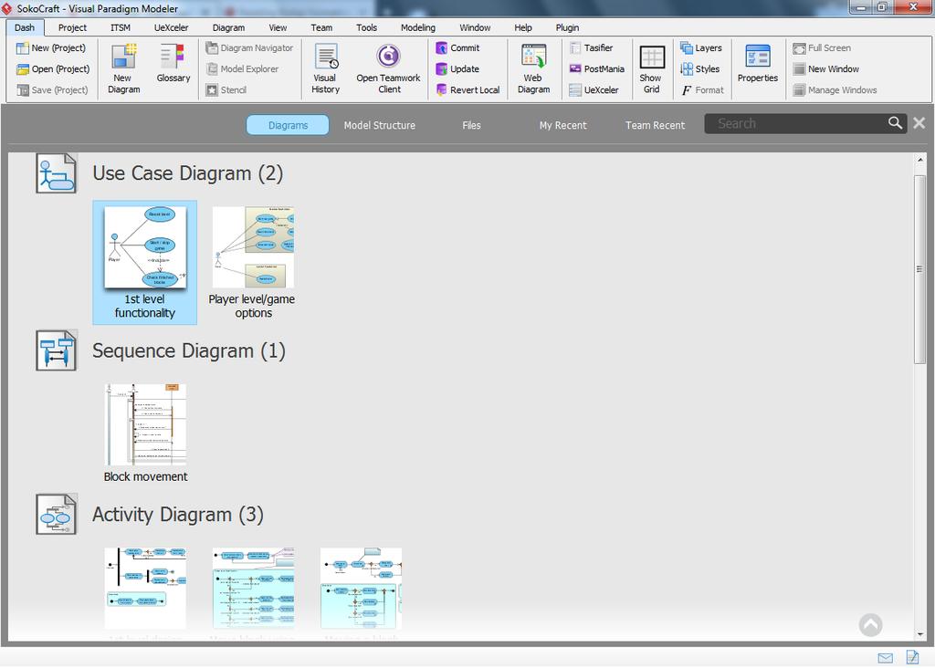
Here you see the diagram overview of a project I’m currently working on. Question: can you determine which diagram(s) are ‘real’ (so: showcasing an actual realized implementation) and which were only meant as either an example or analysis?
Don’t worry if you can’t because I can’t either, and I’m the one who made those ![]()
I don’t recall because I don’t have to, I let VP worry about that for me. How did I do that? Simple: by using a so called model structure:
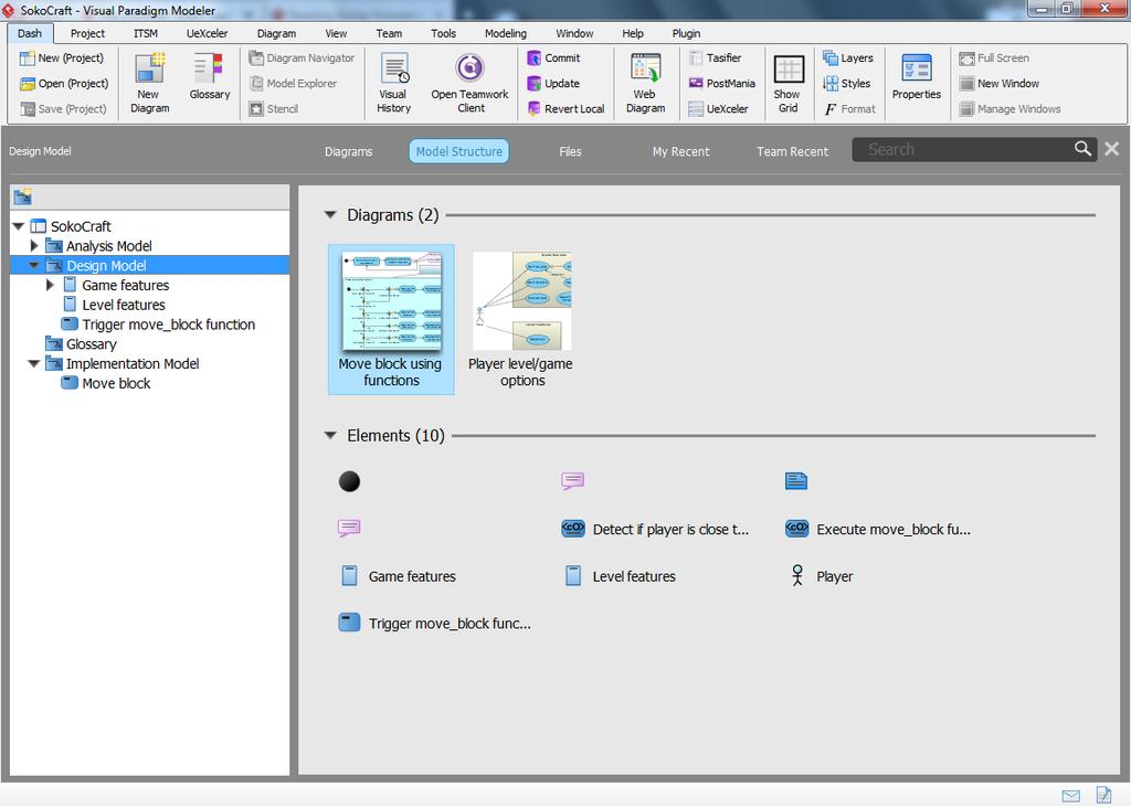
Here you see the same project as before, but this time from within the model structure pane. As you can see I use 3 main models:
- The Analysis model contains my brainstorming, rough (starting) ideas I had about this project. In this particular case that model consists of a textual analysis and a (still to be finished) BPMN diagram which will eventually showcase the entire game level which we’re making.
- The Design model, also shown in the screenshot, contains ideas for the actual design. These aren’t necessarily perfectly working designs, but still working ideas which were eventually used in the actual implementation (either fully or partially). You can consider this section the beta stage of the project.
- And finally the Implementation model; this section contains the overview of the actually working and implemented designs. This showcases how the project has been currently implemented and how it works.
So basically… Even though I have 2 use cases and 3 activity diagrams I don’t have to wonder what each diagram represents, because the model its in describes that for me. This is how I usually keep an overview over my larger projects and diagrams, and it’s a methodology which I can seriously recommend to consider.
How to use this? Easy: right click, and select the option to add a new model. VIsual Paradigm will make this really easy on you and provides the models shown above by default. Of course you can also add your own model names if you want to.
Diagram Info
Have you ever made technical drawings? If so then you probably have seen this concept before, and if you didn’t know already Visual Paradigm supports this feature as well. I think it really helps to make your diagrams look much more professional:
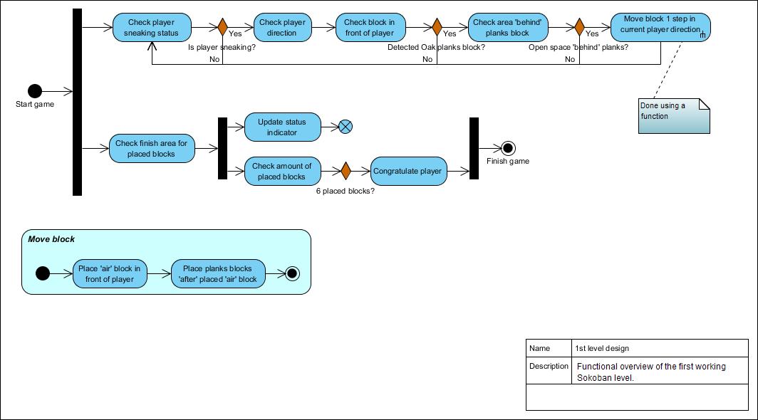
In case you’re wondering: I’m referring to the table in the lower right corner of the screenshot. It shows you the diagram title as well as a short description, this is the same information which you can add or edit in the diagram specifications (right click somewhere in your diagram, then select the “Open Specification” option).
Adding this is quite easy, but I can well imagine that some of you might overlook this option. When working on a diagram scroll down your palette. You will find the ‘Diagram Info’ option in the ‘Common’ category, which is usually listed right below the category which is relevant to the diagram you’re working on (Activity, Use Case, Class, etc.).
Easily overlooked, but I think it can have quite a positive impact.
And there you have it…
Three more tips which are hopefully useful for some of you out there.