I have a data model that has over 2000 entities, which can be grouped into logical ‘areas’. I’d like to have multiple ERDs representing each area, but be able to reference entities from the other ERDs (and be able to see those referenced entities in the diagram). It would be great if changes in the referenced diagram would show up in the referencing one, and when generating the DB that referenced entities/tables were not included. I’m not sure how best to do that… has anyone found a way that works well for them?
That is a huge project, much larger than I have worked with so far. Therefor please keep in mind that I’m definitely not trying to claim that my suggestion is the best. However, I do hope that it might give you some useful ideas.
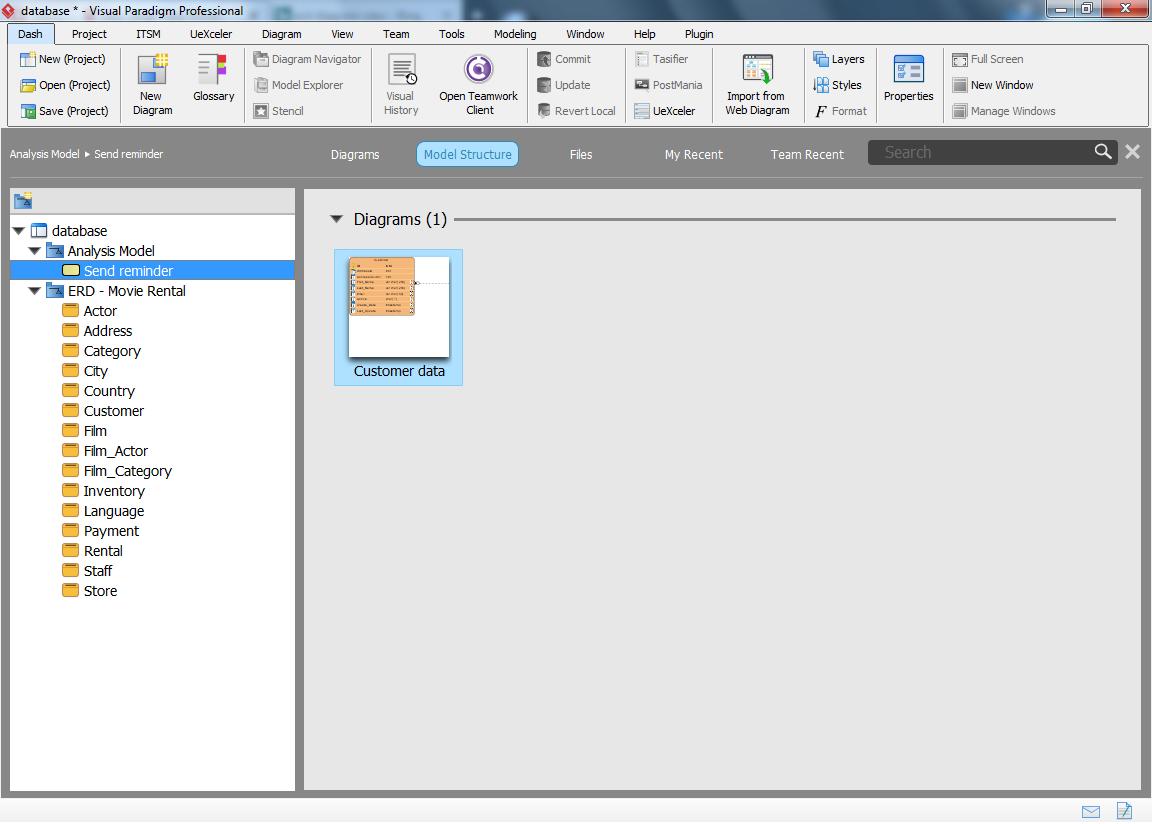
My suggestion is to use ‘models’ which you can use to group your (ERD) diagrams. These are most easily accessed from within the project browser (control-shift-b) and then selecting the “model structure” tab, shown below the toolbar:
What you’re seeing here: “Movie Rental” is an example ERD diagram which I downloaded from Visual Paradigm’s community circle. It resides in the model “ERD - Movie Rental”, which is why all those model elements (entities) are shown.
This leads up to my second suggestion: re-using model elements. In the ‘Analysis Model’ I created a BPMN diagram which in its turn links to “Customer data”, another ERD diagram. But as you can see this diagram has no associated entities (no elements are shown).
That’s because I re-used the elements from the original diagram (follow the previous link to see that one). Doing this is very easy:
Double click to open the resource catalog and select entity to add a new one.
Instead of typing a name press control-space, now all other entities in your project will be shown.
** When the list is too long just type a search string and the list gets filtered
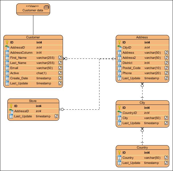
You can’t see it in this export, but the Customer data view is the only real model element in this diagram.
If you’d set this up within Visual Paradigm then you’ll quickly notice several small ‘a’ characters showing in the upper left corner of your entity models. Those ‘a’ symbols mark the so called auxiliary view. This means that you’re basically working with a copy of the original. However, any changes made to the element itself will also propagate throughout all the other views and the master view (=the original element).
This will allow you to work with several different ERD diagrams without having to bother yourself with keeping every entity element synchronized with the rest.
Also noteworthy: If you add 2 entity elements which so happen to share a relation in the original diagram then that relationship will also be automatically created in your new diagram. However, you can easily remove it again without any consequences to the original. Simply because you’re working with another diagram (and using another view).
Finally… Generating databases (or SQL) will only be done on a per (ERD) diagram basis. So if I were to create a database for my original diagram (“ERD - Movie Rental”) then it will completely ignore my other diagrams (and their auxiliary views). And vice versa of course.
As Peter said, you can add auxiliary view to diagram, this will create copy of “view” for the same entity. You can also use color legend to represent different logical areas.
So thank you so much for your replies. I apologise for not replying sooner but I have been trying things out after your suggestions. I have ended up creating separate projects for defined areas - there will probably be around 10 or so - and within each project I have created multiple ERDs - one for each sub-area within it. So I will end up creating all of the entities for an area within the one project, but selectively displaying them in the relevant ERD. Any entities that span more than one sub-area can be duplicated across the ERDs without duplicating the generated DDL. I colour-coded the entities so that it was clear which sub-area they ‘belonged’ to.
For instances where an entity from one project (project A) needs to reference a entity from another project (project B), I found I could use the ‘Referenced Project’ option, and by doing that I could add entities to my ERD from external projects. Doing this also means that if I change the referenced entity back in project A, the change propagates to project B.
All seems to be good. If I’ve missed anything though do let me know